RED-D-ARC DC-600
RED-D-ARC DC-600
RED-D-ARC DC-600

Create successful ePaper yourself
Turn your PDF publications into a flip-book with our unique Google optimized e-Paper software.
A-6<br />
AUXILIARY POWER AND<br />
CONTROL CONNECTIONS<br />
Located at the left side of the front of the welder<br />
behind a hinged cover is a 115VAC duplex receptacle<br />
for auxiliary power (60 Hertz Models only). On the<br />
right side of the case front is a 14 Pin MS type receptacle<br />
for connection of auxiliary equipment such as<br />
wire feeders. Also, terminal strips with 115VAC and<br />
connections for auxiliary equipment are located<br />
behind the hinged access panel on the right side of<br />
the case front. (see Auxiliary Power Table for details)<br />
AUXILIARY POWER TABLE<br />
Voltage and Circuit Breaker Ratings at Auxiliary Power<br />
Connections for Various Models<br />
Auxiliary<br />
Power<br />
Connections<br />
60 Hz<br />
Models<br />
INSTALLATION<br />
PIN LEAD NO. FUNCTION<br />
TERMINAL STRIPS<br />
A-6<br />
A 32 115 VAC<br />
B GND Chassis Connection<br />
C 2 Trigger Circuit<br />
D 4 Trigger Circuit<br />
E 77 Output Control<br />
F 76 Output Control<br />
G 75 Output Control<br />
H 21 Work Sense Connection 2<br />
I 41 42 VAC<br />
J 31 115 VAC 1.<br />
K 42 42 VAC<br />
L --- ---<br />
M --- ---<br />
N --- ---<br />
At Duplex<br />
Receptacle<br />
Terminal strip<br />
terminals 31 & 32<br />
MS-Receptacle<br />
pins A & J<br />
MS-Receptacle<br />
pins I & K<br />
115V 15A<br />
115V 15A<br />
115V 15A<br />
42V 10A<br />
115VAC DUPLEX RECEPTACLE (60 HERTZ<br />
MODELS ONLY)<br />
The 115VAC duplex receptacle is protected by a circuit<br />
breaker located on the nameplate. The receptacle<br />
is a NEMA 5-15R.<br />
14 PIN MS TYPE RECEPTACLE<br />
(For MS3106A-20-27PX Plug. L.E.C. Part #S12020-32)<br />
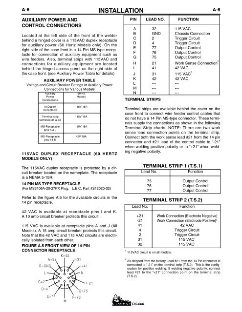
Refer to the figure A.5 for the available circuits in the<br />
14 pin receptacle.<br />
42 VAC is available at receptacle pins I and K.<br />
A 10 amp circuit breaker protects this circuit.<br />
115 VAC is available at receptacle pins A and J (All<br />
Models). A 15 amp circuit breaker protects this circuit.<br />
Note that the 42 VAC and 115 VAC circuits are electrically<br />
isolated from each other.<br />
FIGURE A.5 FRONT VIEW OF 14-PIN<br />
CONNECTOR RECEPTACLE<br />
B=GND<br />
L<br />
A=32<br />
K=42<br />
J=31<br />
I=41<br />
N<br />
Terminal strips are available behind the cover on the<br />
case front to connect wire feeder control cables that<br />
do not have a 14 Pin MS-type connector. These terminals<br />
supply the connections as shown in the following<br />
Terminal Strip charts. NOTE: There are two work<br />
sense lead connection points on the terminal strip.<br />
Connect both the work sense lead #21 from the 14 pin<br />
connector and #21 lead of the control cable to “-21”<br />
when welding positive polarity or to “+21” when welding<br />
negative polarity.<br />
TERMINAL STRIP 1 (T.S.1)<br />
Lead No.<br />
Function<br />
75 Output Control<br />
76 Output Control<br />
77 Output Control<br />
TERMINAL STRIP 2 (T.S.2)<br />
Lead No.<br />
Function<br />
+21 Work Connection (Electrode Negative)<br />
-21 Work Connection (Electrode Positive) 2<br />
41 42 VAC<br />
4 Trigger Circuit<br />
2 Trigger Circuit<br />
31 115 VAC 1<br />
32 115 VAC 1<br />
1.<br />
115VAC circuit is on all models.<br />
2.<br />
As shipped from the factory Lead #21 from the 14 Pin connector is<br />
connected to “-21” on the terminal strip (T.S.2). This is the configuration<br />
for positive welding. If welding negative polarity, connect<br />
lead #21 to the “+21” connection point on the terminal strip<br />
(T.S.2).<br />
C=2<br />
H=21<br />
D=4<br />
G=75<br />
E=77<br />
M<br />
F=76<br />
<strong>DC</strong>-<strong>600</strong>