RED-D-ARC DC-600
RED-D-ARC DC-600
RED-D-ARC DC-600

You also want an ePaper? Increase the reach of your titles
YUMPU automatically turns print PDFs into web optimized ePapers that Google loves.
C-2<br />
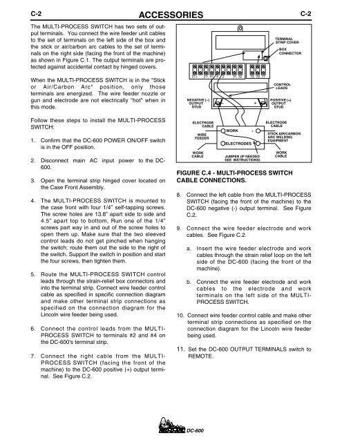
The MULTI-PROCESS SWITCH has two sets of output<br />
terminals. You connect the wire feeder unit cables<br />
to the set of terminals on the left side of the box and<br />
the stick or air/carbon arc cables to the set of terminals<br />
on the right side (facing the front of the machine)<br />
as shown in Figure C.1. The output terminals are protected<br />
against accidental contact by hinged covers.<br />
ACCESSORIES<br />
TERMINAL<br />
STRIP COVER<br />
BOX<br />
CONNECTOR<br />
C-2<br />
When the MULTI-PROCESS SWITCH is in the "Stick<br />
or Air/Carbon Arc" position, only those<br />
terminals are energized. The wire feeder nozzle or<br />
gun and electrode are not electrically "hot" when in<br />
this mode.<br />
21+ 21- 41 4 2 31 32 75 76 77<br />
NEGATIVE (–)<br />
OUTPUT<br />
STUD<br />
– +<br />
CONTROL<br />
LEADS<br />
POSITIVE (+)<br />
OUTPUT<br />
STUD<br />
Follow these steps to install the MULTI-PROCESS<br />
SWITCH:<br />
1. Confirm that the <strong>DC</strong>-<strong>600</strong> POWER ON/OFF switch<br />
is in the OFF position.<br />
2. Disconnect main AC input power to the <strong>DC</strong>-<br />
<strong>600</strong>.<br />
3. Open the terminal strip hinged cover located on<br />
the Case Front Assembly.<br />
4. The MULTI-PROCESS SWITCH is mounted to<br />
the case front with four 1/4” self-tapping screws.<br />
The screw holes are 13.8” apart side to side and<br />
4.5” apart top to bottom, Run one of the 1/4”<br />
screws part way in and out of the screw holes to<br />
open them up. Make sure that the two sleeved<br />
control leads do not get pinched when hanging<br />
the switch; route them out the side to the right of<br />
the switch. Support the switch in position and start<br />
the four screws, then tighten them.<br />
5. Route the MULTI-PROCESS SWITCH control<br />
leads through the strain-relief box connectors and<br />
into the terminal strip. Connect wire feeder control<br />
cable as specified in specific connection diagram<br />
and make other terminal strip connections as<br />
specified on the connection diagram for the<br />
Lincoln wire feeder being used.<br />
6. Connect the control leads from the MULTI-<br />
PROCESS SWITCH to terminals #2 and #4 on<br />
the <strong>DC</strong>-<strong>600</strong>'s terminal strip.<br />
7. Connect the right cable from the MULTI-<br />
PROCESS SWITCH (facing the front of the<br />
machine) to the <strong>DC</strong>-<strong>600</strong> positive (+) output terminal.<br />
See Figure C.2.<br />
ELECTRODE<br />
CABLE<br />
WIRE<br />
FEEDER<br />
WORK<br />
CABLE<br />
WORK<br />
ELECTRODES<br />
JUMPER (IF NEEDED<br />
SEE INSTRUCTIONS)<br />
ELECTRODE<br />
CABLE<br />
WORK<br />
CABLE<br />
FIGURE C.4 - MULTI-PROCESS SWITCH<br />
CABLE CONNECTIONS.<br />
8. Connect the left cable from the MULTI-PROCESS<br />
SWITCH (facing the front of the machine) to the<br />
<strong>DC</strong>-<strong>600</strong> negative (-) output terminal. See Figure<br />
C.2.<br />
9. Connect the wire feeder electrode and work<br />
cables. See Figure C.2.<br />
a. Insert the wire feeder electrode and work<br />
cables through the strain relief loop on the left<br />
side of the <strong>DC</strong>-<strong>600</strong> (facing the front of the<br />
machine).<br />
b. Connect the wire feeder electrode and work<br />
cables to the electrode and work<br />
terminals on the left side of the MULTI-<br />
PROCESS SWITCH.<br />
10. Connect wire feeder control cable and make other<br />
terminal strip connections as specified on the<br />
connection diagram for the Lincoln wire feeder<br />
being used.<br />
11. Set the <strong>DC</strong>-<strong>600</strong> OUTPUT TERMINALS switch to<br />
REMOTE.<br />
+<br />
STICK AIR/CARBON<br />
<strong>ARC</strong> WELDING<br />
EQUIPMENT<br />
<strong>DC</strong>-<strong>600</strong>