Low Cost Torch Height Control Install and Setup Manual - CandCNC
Low Cost Torch Height Control Install and Setup Manual - CandCNC
Low Cost Torch Height Control Install and Setup Manual - CandCNC

You also want an ePaper? Increase the reach of your titles
YUMPU automatically turns print PDFs into web optimized ePapers that Google loves.
<strong>Install</strong>ing Mach 3 software<br />
MACH Pinouts<br />
To implement THC control through MACH there are four signals required:<br />
THC ON (this is the ARC OK signal) [INPUT]<br />
THC UP [INPUT]<br />
THC DOWN [INPUT]<br />
TORCH ON (<strong>Torch</strong> Fire) [OUTPUT] typically mapped to Output1 <strong>and</strong> activated by TORCH<br />
BUTTON in MACH or an M03 for ON <strong>and</strong> M05 for Off in the G-code<br />
The output selected to fire the torch through output1 is whatever output pin on the parallel port<br />
you physically connect to the TORCH ON input of the LCTHC. See the LCTHC hookup details<br />
to identify that input Often all that is needed is to use an existing output on your BoB <strong>and</strong> map<br />
it to turn on the torch. It does not have to be the same output that turns on your router/spindle if<br />
you use a mixed mode machine.<br />
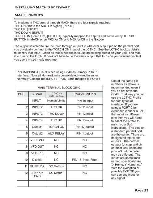
PIN MAPPING CHART when using G540 as Primary PORT1<br />
interface. Note all Homes/Limits consolidated (wired in series<br />
Normally Closed) into INPUT1 (POS1) <strong>and</strong> mapped to PORT1<br />
POS<br />
SIGNAL<br />
MAIN TERMINAL BLOCK G540<br />
LCTHC via<br />
G540 Interface<br />
Parallel Port PIN<br />
1 INPUT1 Homes/Limits PIN 10 input<br />
2 INPUT2 ARC OK PIN 11 input<br />
3 INPUT3 THC DOWN PIN 12 input<br />
4 INPUT4 THC UP PIN 13 input<br />
5 Output1 TORCH ON PIN 17 output<br />
6 Output2 AUX RELAY PIN 1 output<br />
7 VFD GND NC NC<br />
8 VFD OUT NC NC<br />
9 VFD +10 NC NC<br />
10 Disable NC PIN 15 input-Fault<br />
11 SUPPLY + DC Motor + NC<br />
12 SUPPLY<br />
GND<br />
DC Motor -<br />
NC<br />
Use of the same pin<br />
numbers as above is<br />
recommended even if<br />
you do not have the<br />
G540. That way you can<br />
use the LCTHC Profile<br />
for both types of<br />
interface. If you are<br />
using a PORT 2 for<br />
exp<strong>and</strong>ed input or a BoB<br />
that requires different<br />
pins then you will need<br />
to adapt the profile to<br />
match your BoB<br />
instructions. The pins on<br />
a st<strong>and</strong>ard parallel port<br />
are the same. There are<br />
designated inputs <strong>and</strong><br />
outputs. The normal<br />
outputs for step <strong>and</strong> dir<br />
on most BoB cards are<br />
pins 2-9 but the order<br />
may be different. The<br />
Inputs are sometimes<br />
named specifically like<br />
“X Home, Y Home, etc”<br />
With the exception of<br />
possibly E-STOP you<br />
can use any input for<br />
any signal<br />
Page 23