IMProVe 2011 - Proceedings
IMProVe 2011 - Proceedings
IMProVe 2011 - Proceedings

Create successful ePaper yourself
Turn your PDF publications into a flip-book with our unique Google optimized e-Paper software.
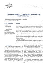
Teaching Product Design and Drawing History<br />
Improving a CAD tool to simplify the design process<br />
of electrical schematics oriented to industrial-machine control<br />
P. Ubieto Artur (a), C. García Hernández (a), A. Fernández Sora (b)<br />
(a) Idergo (I3A), Department of Design and Manufacturing Engineering, University of Zaragoza,<br />
Zaragoza, Spain<br />
(b) Department of Design and Manufacturing Engineering, University of Zaragoza, Zaragoza, Spain<br />
Abstract:<br />
Electrical circuits are graphically described most of the times and the use of some kind of<br />
computer-aided design (CAD) to do it is more than usual. Electrical engineers can be highly<br />
helped in this process with a library of symbols to represent the different components of a<br />
circuit and, wouldn’t be interesting if they could simulate the circuits that they had<br />
graphically represented? We thought so.<br />
For the previous reasons, a tool with just a good library of electrical symbols would be<br />
useful but, if it made possible to test the circuits it could have a great value, both for<br />
professional and educational purposes. This tool is really helpful in the learning process of<br />
our students in Technical Office. In this subject, the Electrical Engineering Degree students<br />
must work on an electrical project which always includes the design of some kind of<br />
circuit. The tool makes possible to simulate those circuits within the CAD software, so it is<br />
easy, fast and safe to try different designs by changing the graphical symbols and/or their<br />
connections.<br />
Those features make the tool interesting in an educational environment, but not only.<br />
Professional engineers can also find this tool interesting because it can be used in the<br />
design process and as a tool for graphical representation. The improvements in the tool<br />
included, e.g., the wire simulation within the electrical box, making the circuit safer and<br />
cheaper.<br />
Keywords: Electrical diagrams, Simulator, CAD, Software.<br />
Corresponding Author: Pedro Ubieto Artur<br />
Tel.: (+34) 976761000<br />
Fax.: (+34) 976762620<br />
pubieto@unizar.es<br />
Idergo (I3A) - Department of Design and Manufacturing Engineering, University of Zaragoza, María<br />
de Luna 3, 50018 Zaragoza (Spain).<br />
June 15 th – 17 th , <strong>2011</strong>, Venice, Italy<br />
133<br />
<strong>IMProVe</strong> <strong>2011</strong> - <strong>Proceedings</strong>