

TCAEY-THAEY 115÷238 - Rhoss
TCAEY-THAEY 115÷238 - Rhoss
TCAEY-THAEY 115÷238 - Rhoss

Create successful ePaper yourself
Turn your PDF publications into a flip-book with our unique Google optimized e-Paper software.
<strong>TCAEY</strong>-<strong>THAEY</strong> 115÷233<br />
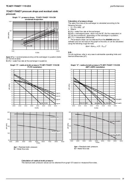
<strong>TCAEY</strong>-<strong>THAEY</strong> pressure drops and residual static<br />
pressure<br />
1000<br />
100<br />
10<br />
Graph “1”: pr essur e drops, <strong>TCAEY</strong>-<strong>THAEY</strong> 115÷238<br />
condenser/evaporator<br />
130<br />
133,233,238<br />
122<br />
124<br />
127<br />
1<br />
1000 10000<br />
G (l/h)<br />
Δpw ( kPa) = nominal press ure drop at t he exchanger in question (table<br />
on Tec hnic al data):<br />
G (l/h) = water fl ow rate at the exc hanger in questi on;<br />
Graph “2”: r esidu al st atic pr essur e TC AEY-<strong>THAEY</strong> 115÷238<br />
P1-P2 instal lation<br />
200<br />
190<br />
180<br />
170<br />
160<br />
150<br />
140<br />
130<br />
120<br />
110<br />
100<br />
90<br />
80<br />
130 P1<br />
127 P1<br />
70<br />
60<br />
124 P1<br />
50<br />
40<br />
115-117 P1<br />
122 P1<br />
2500 3000 3500 4000 4500 5000 5500 6000<br />
G (l/h)<br />
performances<br />
Calculation of pr essur e drops<br />
The wat er flow rate at t he exchanger is c alculat ed accordi ng to t he<br />
followi ng formula:<br />
○ G = (Q x 860) : ΔT<br />
• Wher e:<br />
G (l/h) = water fl ow rate at the exc hanger;<br />
Q (kW) = exchanged power, which may be QF (for the evaporat or) or<br />
QT (for the condens er), depending on t he exchanger in question;<br />
ΔT (°C) = temperature diff erential;<br />
○ The pr essure drops can be obtai ned from t he RHOSS selection<br />
soft ware and can be read on the graph to the side, or c an be calculated<br />
using the following rough for mula:<br />
Δpw = Δpw nom x (G : G nom )²<br />
N.B.:<br />
For all machines, ref er in any c ase to admissible operating limits and<br />
thermal dif ferences (ΔT).<br />
Graph “2”: r esidu al st atic pr essur e TC AEY-<strong>THAEY</strong> 115÷238<br />
ASP1-ASP2 installation<br />
200<br />
190<br />
180<br />
170<br />
160<br />
150<br />
140<br />
130<br />
120<br />
110<br />
100<br />
90<br />
80<br />
70<br />
60<br />
130 ASP1<br />
50<br />
115-117 ASP1 122 ASP1 124 ASP1 127 ASP1<br />
40<br />
2500 3000 3500 4000 4500 5000 5500 6000<br />
G (l/h)<br />
250<br />
250<br />
200<br />
133,233,238 P2<br />
200<br />
133,233,238 ASP2<br />
150<br />
150<br />
100<br />
133,233,238 P1<br />
100<br />
133,233,238 ASP1<br />
50<br />
1000 2000 3000 4000 5000 6000 7000 8000 9000<br />
G (l/h)<br />
Δpr = Residual st atic pressure<br />
G = Water flow rate<br />
50<br />
1000 2000 3000 4000 5000 6000 7000 8000 9000<br />
G (l/h)<br />
Δpr = Residual st atic pressure<br />
G = Water flow rate<br />
Calculation of r esidu al st atic pr essur e<br />
The residual st atic pressure values can be obt ained from graph “2” based on measured flow rates.<br />
35


