

TCAEY-THAEY 115÷238 - Rhoss
TCAEY-THAEY 115÷238 - Rhoss
TCAEY-THAEY 115÷238 - Rhoss

Create successful ePaper yourself
Turn your PDF publications into a flip-book with our unique Google optimized e-Paper software.
<strong>TCAEY</strong>-<strong>THAEY</strong> 133<br />
electrical connections<br />
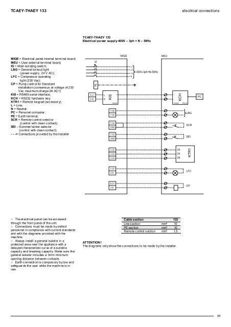
<strong>TCAEY</strong>-<strong>THAEY</strong> 133<br />
Electrical po wer supply 400V – 3ph + N – 50Hz<br />
MIQE = Electrical panel int ernal termi nal board;<br />
MEU = User external ter minal board;<br />
IG = Main isolating switch;<br />
LBG = General lockout light<br />
( power s uppl y 24 V AC);<br />
LFC = Compress or operating<br />
light (230 Vac);<br />
CP = Pump c ontr ol for Standard<br />
inst allation (consens us at voltage of 230<br />
Vac maxi mum charge 2A AC1)<br />
KIS = RS485 s erial interface;<br />
KCH = RS232 hardware key;<br />
KTR1 = Remote keypad (accessor y);<br />
L = Line;<br />
N = Neutral;<br />
PC = Personal comput er;<br />
PE = Earth terminal;<br />
SCR = Remote control selector<br />
(c ontrol with clean c ontact);<br />
SEI – Summer/wint er selec tor<br />
(control with clean contac t);<br />
- - -= Connections pr ovided by the inst aller<br />
PE IG<br />
3.L1 L<br />
3.N N<br />
KIS<br />
+<br />
-<br />
RS485<br />
7.06<br />
7.05<br />
7.04<br />
GND<br />
7.02<br />
GND<br />
MIQE<br />
L1<br />
L2<br />
L3<br />
N<br />
400V-3ph+N-50Hz<br />
MEU<br />
+<br />
-<br />
RS485<br />
KCH<br />
RS232<br />
LBG<br />
SCR<br />
SEI<br />
PC<br />
3.02<br />
3.03<br />
3.04<br />
25<br />
24<br />
26<br />
KTR1<br />
7.07<br />
3 N<br />
LFC<br />
8.01<br />
3 N<br />
CP<br />
○ The el ectrical panel can be acc essed<br />
through the front panel of the unit.<br />
○ Connections must be made by skilled<br />
personnel i n compliance wit h current st andards<br />
and wit h t he diagrams provided wit h t he<br />
mac hine.<br />
○ Always install a general isolator in a<br />
protect ed area near t he applianc e with a<br />
delayed c haract eristic cur ve of a suit abl e<br />
capacit y and breaking c apacit y. Make sure the<br />
general isolator includes a 3mm mini mum<br />
opening dist ance bet ween c ont acts.<br />
○ Earth c onnecti on is c ompuls ory by law and<br />
safeguar ds the user while the machi ne is in<br />
use.<br />
Cable section 133<br />
Line s ection mm² 10<br />
PE sec tion mm² 10<br />
Remote c ontrol s ection mm² 1,5<br />
ATTENTION !<br />
The di agrams onl y show t he c onnecti ons t o be made by t he i nstaller.<br />
54


