

TCAEY-THAEY 115÷238 - Rhoss
TCAEY-THAEY 115÷238 - Rhoss
TCAEY-THAEY 115÷238 - Rhoss

Create successful ePaper yourself
Turn your PDF publications into a flip-book with our unique Google optimized e-Paper software.
GND<br />
GND<br />
!<br />
ALARM<br />
Prg<br />
ON<br />
OFF<br />
MODE<br />
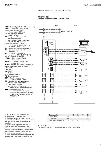
TXAEY 117÷133<br />
electrical connections<br />
Electric connections in TXAEY models<br />
TXAEY 117÷133<br />
Electrical po wer supply 400V – 3ph + N – 50Hz<br />
MIQE = Electrical panel int ernal termi nal board;<br />
MEU = User external ter minal board;<br />
LBG = General lockout light<br />
( power s uppl y 230 Vac);<br />
LFC = Compress or operating<br />
light (230 Vac);<br />
CP = Pump c ontr ol for model 133<br />
(Standard i nstallati on)<br />
(consens us at volt age of 230 Vac<br />
maxi mum charge 2A AC1);<br />
CPR = Recover y pump c ontrol<br />
(c onsensus at voltage of 230 Vac<br />
maximum c harge 2A AC 1);<br />
J16 = 6-way t elephone c onnect or (RJ12);<br />
J19 = Connector for insertion of<br />
access ory KSC;<br />
J20 = Connector for insertion of<br />
accessories KRS485, KFTT10, KISI;<br />
KSC = Clock card (accessor y);<br />
KRS485 = Serial int erfac e RS485<br />
(access ory);<br />
KRS232 = C onverter RS485/R S232<br />
(access ory);<br />
KUSB = converter RS485/USB (access ory);<br />
KTR = Remote keyboard (accessor y);<br />
L1 = Line 1;<br />
L2 = Line 2;<br />
L3 = Line 3;<br />
N = Neutral;<br />
PC = Personal comput er;<br />
PE = Earth terminal;<br />
SCR = Remote control selector<br />
(c ontrol with clean c ontact);<br />
SEI = Selector AUTOMATIC / SELECT<br />
(control with cl ean contact);<br />
CR = Recovery consens us<br />
(control with cl ean contact);<br />
- - -= Connecti ons provided by t he ins taller<br />
= 6-wire telephone c abl e<br />
(maximum distance 50 m., for<br />
distanc es which are greater than this<br />
pl ease contact cust omer ser vice at<br />
RHOSS S.p.A.<br />
PE<br />
+<br />
-<br />
KSC<br />
J19<br />
CLOCK CARD<br />
KRS485<br />
7.05<br />
N<br />
7.06<br />
N<br />
7.06<br />
7.07<br />
7.08<br />
7.09<br />
Mod. 133<br />
J20<br />
SERIAL<br />
CARD<br />
ID7 ID8<br />
J8<br />
J16<br />
INTERFACE<br />
PLAN<br />
7.05<br />
N<br />
7.06<br />
N<br />
7.07<br />
7.08<br />
7.09<br />
7.10<br />
Mod. 117130<br />
MIQE<br />
L1<br />
L2<br />
L3<br />
N<br />
400V-3ph+N-50Hz<br />
MEU<br />
+<br />
-<br />
KTR<br />
KRS232<br />
/ KUSB<br />
SCR<br />
SEI<br />
CP<br />
LBG<br />
LFC<br />
CR<br />
CPR<br />
PC<br />
○ The el ectrical panel can be acc essed<br />
through the front panel of the unit.<br />
○ Connections must be made by skilled<br />
personnel i n compliance wit h current st andards<br />
and wit h t he diagrams provided wit h t he<br />
mac hine.<br />
○ Always install a general isolator in a<br />
protect ed area near t he applianc e with a<br />
delayed c haract eristic cur ve of a suit abl e<br />
capacit y and breaking c apacit y. Make sure the<br />
general isolator includes a 3mm mini mum<br />
opening dist ance bet ween c ont acts.<br />
○ Earth c onnecti on is c ompuls ory by law and<br />
safeguar ds the user while the machi ne is in<br />
use.<br />
Cable section 117 124 130 133<br />
Line s ection mm² 4 6 10 10<br />
PE sec tion mm² 4 6 10 10<br />
Remote c ontrol s ection mm² 1,5 1,5 1,5 1,5<br />
ATTENTION !<br />
The di agrams onl y show t he c onnecti ons t o be made by t he i nstaller.<br />
57


