Operating Instructions Non-Contact Safety Switch CET.-AR-...-CH ...
Operating Instructions Non-Contact Safety Switch CET.-AR-...-CH ...
Operating Instructions Non-Contact Safety Switch CET.-AR-...-CH ...

You also want an ePaper? Increase the reach of your titles
YUMPU automatically turns print PDFs into web optimized ePapers that Google loves.
<strong>Operating</strong> <strong>Instructions</strong> <strong>Safety</strong> <strong>Switch</strong> <strong>CET</strong>.-<strong>AR</strong>-...-<strong>CH</strong>-...<br />
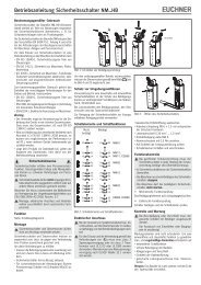
Mounting<br />
Caution!<br />
Caution!<br />
<strong>Safety</strong> switches must not be bypassed (bridging of contacts), turned away,<br />
removed or otherwise rendered ineffective.<br />
ÌÌOn this topic pay attention in particular to the measures for reducing the possibility<br />
of bypassing according to EN 1088:1995.A2:2008, sec. 5.7.<br />
ÌÌThe max. achievable category according to EN 13849-1 depends on the<br />
installation position (see technical data).<br />
Risk of damage to equipment and malfunctions as a result of incorrect installation.<br />
ÌÌ<strong>Safety</strong> switches must not be used as a mechanical end stop. Fit an additional<br />
end stop for the movable part of the safety guard.<br />
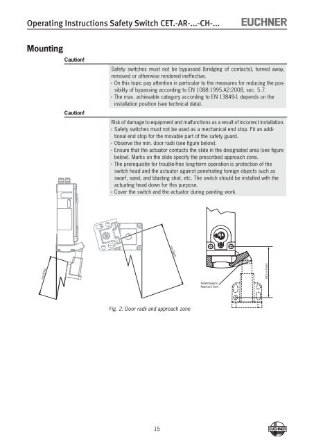
ÌÌObserve the min. door radii (see figure below).<br />
ÌÌEnsure that the actuator contacts the slide in the designated area (see figure<br />
below). Marks on the slide specify the prescribed approach zone.<br />
ÌÌThe prerequisite for trouble-free long-term operation is protection of the<br />
switch head and the actuator against penetrating foreign objects such as<br />
swarf, sand, and blasting shot, etc. The switch should be installed with the<br />
actuating head down for this purpose.<br />
ÌÌCover the switch and the actuator during painting work.<br />
min R800<br />
min R300<br />
74,5 ± 4 mm<br />
Anfahrbereich/<br />
Approach Zone<br />
Fig. 2: Door radii and approach zone<br />
15