Operating Instructions Non-Contact Safety Switch CET.-AR-...-CH ...
Operating Instructions Non-Contact Safety Switch CET.-AR-...-CH ...
Operating Instructions Non-Contact Safety Switch CET.-AR-...-CH ...
You also want an ePaper? Increase the reach of your titles
YUMPU automatically turns print PDFs into web optimized ePapers that Google loves.
<strong>Operating</strong> <strong>Instructions</strong> <strong>Safety</strong> <strong>Switch</strong> <strong>CET</strong>.-<strong>AR</strong>-...-<strong>CH</strong>-...<br />
Important:<br />
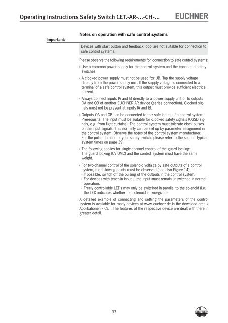
Notes on operation with safe control systems<br />
Devices with start button and feedback loop are not suitable for connection to<br />
safe control systems.<br />
Please observe the following requirements for connection to safe control systems:<br />
ÌÌUse a common power supply for the control system and the connected safety<br />
switches.<br />
ÌÌA clocked power supply must not be used for UB. Tap the supply voltage<br />
directly from the power supply unit. If the supply voltage is connected to a<br />
terminal of a safe control system, this output must provide sufficient electrical<br />
current.<br />
ÌÌAlways connect inputs IA and IB directly to a power supply unit or to outputs<br />
OA and OB of another EU<strong>CH</strong>NER <strong>AR</strong> device (series connection). Clocked signals<br />
must not be present at inputs IA and IB.<br />
ÌÌOutputs OA and OB can be connected to the safe inputs of a control system.<br />
Prerequisite: The input must be suitable for clocked safety signals (OSSD signals,<br />
e.g. from light curtains). The control system must tolerate clock pulses<br />
on the input signals. This normally can be set up by parameter assignment in<br />
the control system. Observe the notes of the control system manufacturer.<br />
For the pulse duration of your safety switch, please refer to the section Typical<br />
system times on page 39.<br />
ÌÌThe following applies for single-channel control of the guard locking:<br />
The guard locking (0V UMC) and the control system must have the same<br />
weight.<br />
ÌÌFor two-channel control of the solenoid voltage by safe outputs of a control<br />
system, the following points must be observed (see also Figure 14):<br />
ÌÌIf possible, switch off the pulsing of the outputs in the control system.<br />
ÌÌFor devices with teach-in input J, the input must remain unswitched in normal<br />
operation.<br />
ÌÌFreely controllable LEDs may only be switched in parallel to the solenoid (i.e.<br />
the LED indicates whether the solenoid is energized).<br />
A detailed example of connecting and setting the parameters of the control<br />
system is available for many devices at www.euchner.de in the download area »<br />
Applikationen » <strong>CET</strong>. The features of the respective device are dealt with there in<br />
greater detail.<br />
33


