Operating Instructions Non-Contact Safety Switch CET.-AR-...-CH ...
Operating Instructions Non-Contact Safety Switch CET.-AR-...-CH ...
Operating Instructions Non-Contact Safety Switch CET.-AR-...-CH ...

You also want an ePaper? Increase the reach of your titles
YUMPU automatically turns print PDFs into web optimized ePapers that Google loves.
<strong>Operating</strong> <strong>Instructions</strong> <strong>Safety</strong> <strong>Switch</strong> <strong>CET</strong>.-<strong>AR</strong>-...-<strong>CH</strong>-...<br />
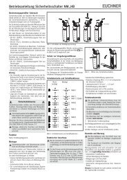
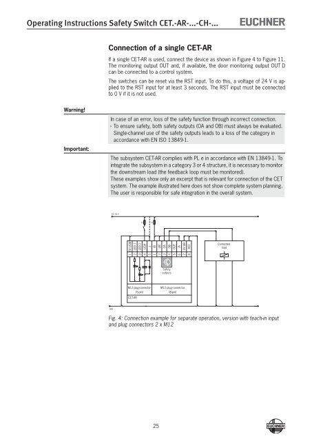
Connection of a single <strong>CET</strong>-<strong>AR</strong><br />
If a single <strong>CET</strong>-<strong>AR</strong> is used, connect the device as shown in Figure 4 to Figure 11.<br />
The monitoring output OUT and, if available, the door monitoring output OUT D<br />
can be connected to a control system.<br />
The switches can be reset via the RST input. To do this, a voltage of 24 V is applied<br />
to the RST input for at least 3 seconds. The RST input must be connected<br />
to 0 V if it is not used.<br />
Warning!<br />
Important:<br />
In case of an error, loss of the safety function through incorrect connection.<br />
ÌÌTo ensure safety, both safety outputs (OA and OB) must always be evaluated.<br />
Single-channel use of the safety outputs leads to a loss of the category in<br />
accordance with EN ISO 13849-1.<br />
The subsystem <strong>CET</strong>-<strong>AR</strong> complies with PL e in accordance with EN 13849-1. To<br />
integrate the subsystem in a category 3 or 4 structure, it is necessary to monitor<br />
the downstream load (the feedback loop must be monitored).<br />
These examples show only an excerpt that is relevant for connection of the <strong>CET</strong><br />
system. The example illustrated here does not show complete system planning.<br />
The user is responsible for safe integration in the overall system.<br />
DC 24 V<br />
-F2<br />
-F1<br />
0V UCM<br />
LED 1<br />
LED 2<br />
UCM<br />
J<br />
IB<br />
UB<br />
OA<br />
OB<br />
OUT<br />
IA<br />
0V UB<br />
RST<br />
Connected<br />
load<br />
1<br />
2<br />
3<br />
4<br />
5<br />
1<br />
2<br />
3<br />
4<br />
5<br />
6<br />
7<br />
8<br />
<strong>Safety</strong><br />
outputs<br />
M12 plug-connector<br />
(5-pin)<br />
<strong>CET</strong>-<strong>AR</strong><br />
M12 plug-connector<br />
(8-pin)<br />
GND<br />
Fig. 4: Connection example for separate operation, version with teach-in input<br />
and plug connectors 2 x M12<br />
25