Operating Instructions Non-Contact Safety Switch CET.-AR-...-CH ...
Operating Instructions Non-Contact Safety Switch CET.-AR-...-CH ...
Operating Instructions Non-Contact Safety Switch CET.-AR-...-CH ...

Create successful ePaper yourself
Turn your PDF publications into a flip-book with our unique Google optimized e-Paper software.
<strong>Operating</strong> <strong>Instructions</strong> <strong>Safety</strong> <strong>Switch</strong> <strong>CET</strong>.-<strong>AR</strong>-...-<strong>CH</strong>-...<br />
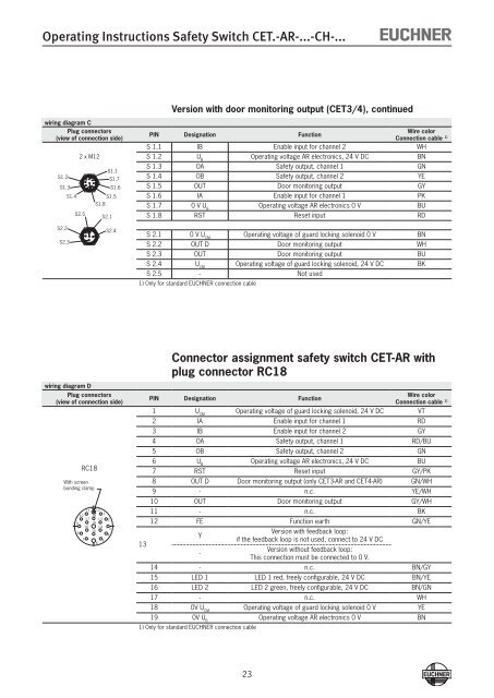
Version with door monitoring output (<strong>CET</strong>3/4), continued<br />
wiring diagram C<br />
Plug connectors<br />
(view of connection side)<br />
S1.2<br />
S1.3<br />
S1.4<br />
2 x M12<br />
S2.5<br />
S1.8<br />
S1.5<br />
S2.1<br />
S1.1<br />
S1.7<br />
S1.6<br />
PIN Designation Function<br />
Wire color<br />
Connection cable 1)<br />
S 1.1 IB Enable input for channel 2 WH<br />
S 1.2 U B<br />
<strong>Operating</strong> voltage <strong>AR</strong> electronics, 24 V DC BN<br />
S 1.3 OA <strong>Safety</strong> output, channel 1 GN<br />
S 1.4 OB <strong>Safety</strong> output, channel 2 YE<br />
S 1.5 OUT Door monitoring output GY<br />
S 1.6 IA Enable input for channel 1 PK<br />
S 1.7 0 V U B<br />
<strong>Operating</strong> voltage <strong>AR</strong> electronics 0 V BU<br />
S 1.8 RST Reset input RD<br />
S2.2<br />
S2.3<br />
S2.4<br />
S 2.1 0 V U CM<br />
<strong>Operating</strong> voltage of guard locking solenoid 0 V BN<br />
S 2.2 OUT D Door monitoring output WH<br />
S 2.3 OUT Door monitoring output BU<br />
S 2.4 U CM<br />
<strong>Operating</strong> voltage of guard locking solenoid, 24 V DC BK<br />
S 2.5 - Not used<br />
1) Only for standard EU<strong>CH</strong>NER connection cable<br />
wiring diagram D<br />
Plug connectors<br />
(view of connection side)<br />
RC18<br />
With screen<br />
bonding clamp<br />
11 12<br />
1<br />
10 18<br />
17 13 2<br />
9 19<br />
16 14<br />
3<br />
15<br />
8<br />
4<br />
7 5<br />
6<br />
13<br />
Connector assignment safety switch <strong>CET</strong>-<strong>AR</strong> with<br />
plug connector RC18<br />
PIN Designation Function<br />
Wire color<br />
Connection cable 1)<br />
1 U CM<br />
<strong>Operating</strong> voltage of guard locking solenoid, 24 V DC VT<br />
2 IA Enable input for channel 1 RD<br />
3 IB Enable input for channel 2 GY<br />
4 OA <strong>Safety</strong> output, channel 1 RD/BU<br />
5 OB <strong>Safety</strong> output, channel 2 GN<br />
6 U B<br />
<strong>Operating</strong> voltage <strong>AR</strong> electronics, 24 V DC BU<br />
7 RST Reset input GY/PK<br />
8 OUT D Door monitoring output (only <strong>CET</strong>3-<strong>AR</strong> and <strong>CET</strong>4-<strong>AR</strong>) GN/WH<br />
9 - n.c. YE/WH<br />
10 OUT Door monitoring output GY/WH<br />
11 - n.c. BK<br />
12 FE Function earth GN/YE<br />
Y<br />
-<br />
Version with feedback loop:<br />
if the feedback loop is not used, connect to 24 V DC<br />
Version without feedback loop:<br />
This connection must be connected to 0 V.<br />
14 - n.c. BN/GY<br />
15 LED 1 LED 1 red, freely configurable, 24 V DC BN/YE<br />
16 LED 2 LED 2 green, freely configurable, 24 V DC BN/GN<br />
17 - n.c. WH<br />
18 0V U CM<br />
<strong>Operating</strong> voltage of guard locking solenoid 0 V YE<br />
19 0V U B<br />
<strong>Operating</strong> voltage <strong>AR</strong> electronics 0 V BN<br />
1) Only for standard EU<strong>CH</strong>NER connection cable<br />
23