Operating Instructions Non-Contact Safety Switch CET.-AR-...-CH ...
Operating Instructions Non-Contact Safety Switch CET.-AR-...-CH ...
Operating Instructions Non-Contact Safety Switch CET.-AR-...-CH ...

Create successful ePaper yourself
Turn your PDF publications into a flip-book with our unique Google optimized e-Paper software.
<strong>Operating</strong> <strong>Instructions</strong> <strong>Safety</strong> <strong>Switch</strong> <strong>CET</strong>.-<strong>AR</strong>-...-<strong>CH</strong>-...<br />
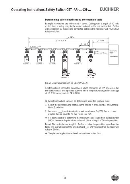
Determining cable lengths using the example table<br />
Example: 6 switches are to be used in series. Cabling with a length of 40 m is<br />
routed from a safety relay in the control cabinet to the last switch (#6). Cables<br />
with a length of 20 m each are connected between the individual CES-<strong>AR</strong>/<strong>CET</strong>-<strong>AR</strong><br />
safety switches.<br />
l max<br />
= 140 m<br />
l 2<br />
= 5 x 20 m<br />
l 1<br />
= 40 m<br />
l n<br />
= 20 m<br />
u n<br />
= min. 19,2 V<br />
i OA/OB<br />
= min. 75 mA<br />
Sicherheitsrelais<br />
<strong>Safety</strong> Relay<br />
CES-<strong>AR</strong> # 1<br />
CES-<strong>AR</strong> # 2<br />
CES-<strong>AR</strong> # 3<br />
CES-<strong>AR</strong> # 5<br />
<strong>CET</strong>-<strong>AR</strong> # 4<br />
<strong>CET</strong>-<strong>AR</strong> # 6<br />
Fig. 3: Circuit example with six CES-<strong>AR</strong>/<strong>CET</strong>-<strong>AR</strong><br />
A safety relay is connected downstream which consumes 75 mA at each of the<br />
two safety inputs. This operates over the whole temperature range with a voltage<br />
of 19.2 V (corresponds to 24 V -20%).<br />
All the relevant values can now be determined using the example table:<br />
1. Select the corresponding section in the column n (max. number of switches).<br />
Here: 6 switches.<br />
2. In column I OA/OB<br />
(possible output current per channel OA/OB), find a current<br />
greater than or equal to 75 mA. Here: 100 mA.<br />
¨¨<br />
It is then possible to determine the maximum cable length from the last switch<br />
(#6) to the control system from column l 1<br />
. Here: a length of 50 m is permitted.<br />
Result: The desired cable length l 1<br />
of 40 m is below the permitted value from the<br />
table. The overall length of the switch chain l max<br />
of 140 m is less than the maximum<br />
value of 200 m.<br />
¨¨<br />
The planned application is therefore functional in this form.<br />
21