digital compensation of dynamic acquisition errors at the front-end of ...
digital compensation of dynamic acquisition errors at the front-end of ...
digital compensation of dynamic acquisition errors at the front-end of ...
You also want an ePaper? Increase the reach of your titles
YUMPU automatically turns print PDFs into web optimized ePapers that Google loves.
26 Chapter 2: Nonlinearity <strong>at</strong> <strong>the</strong> ADC’s Front-End<br />
transferred to <strong>the</strong> output using switch M 3 . Therefore, V out is equal to <strong>the</strong> capacitor<br />
voltage <strong>at</strong> <strong>the</strong> <strong>end</strong> <strong>of</strong> <strong>the</strong> tracking phase. Using samples <strong>of</strong> <strong>the</strong> input and output voltage<br />
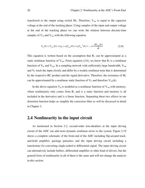
<strong>at</strong> <strong>the</strong> <strong>end</strong> <strong>of</strong> <strong>the</strong> tracking phase we can write <strong>the</strong> rel<strong>at</strong>ion between discrete-time<br />
samples <strong>of</strong> V in and V out with <strong>the</strong> following equ<strong>at</strong>ion<br />
2 dVout<br />
( k)<br />
Vin<br />
( k)<br />
= Vout<br />
( k)<br />
+ ( a0 + a1V<br />
out<br />
( k)<br />
+ a2Vout<br />
( k)<br />
+ ...) ×<br />
(2.8)<br />
dt<br />
This equ<strong>at</strong>ion is written based on <strong>the</strong> assumption th<strong>at</strong> R 1 can be approxim<strong>at</strong>ed as a<br />
st<strong>at</strong>ic nonlinear function <strong>of</strong> V out . From equ<strong>at</strong>ion (2.6), we know th<strong>at</strong> R 1 is a nonlinear<br />
function <strong>of</strong> V in and V top . In a sampling network with sufficiently large bandwidth, V top<br />
and V C track <strong>the</strong> input closely and differ by a weakly nonlinear term th<strong>at</strong> is determined<br />
by <strong>the</strong> respective RC product and <strong>the</strong> signal deriv<strong>at</strong>ive. Therefore, <strong>the</strong> resistance <strong>of</strong> M 1<br />
can be approxim<strong>at</strong>ed by a nonlinear st<strong>at</strong>ic function <strong>of</strong> V C and <strong>the</strong>refore V out (k).<br />
In <strong>the</strong> above equ<strong>at</strong>ion V in is modeled as a nonlinear function <strong>of</strong> V out with memory,<br />
where nonlinearity only comes from R 1 and is a st<strong>at</strong>ic function and memory is all<br />
included in <strong>the</strong> deriv<strong>at</strong>ive and is a linear function. Separ<strong>at</strong>ing <strong>the</strong>se two effects in our<br />
distortion function helps us simplify <strong>the</strong> correction filter as will be discussed in detail<br />
in Chapter 3.<br />
2.4 Nonlinearity in <strong>the</strong> input circuit<br />
As mentioned in Section 2.2, second-order non-idealities <strong>at</strong> <strong>the</strong> input driving<br />
circuit <strong>of</strong> <strong>the</strong> ADC can add more <strong>dynamic</strong> nonlinear <strong>errors</strong> to <strong>the</strong> system. Figure 2.19<br />
shows a complete schem<strong>at</strong>ic <strong>of</strong> <strong>the</strong> <strong>front</strong>-<strong>end</strong> <strong>of</strong> <strong>the</strong> ADC including flip-around trackand-hold<br />
amplifier, package parasitics and <strong>the</strong> input driving circuit including a<br />
transformer for converting single-<strong>end</strong>ed to differential signal. The input driving circuit<br />
can altern<strong>at</strong>ively include buffers, differential amplifier or o<strong>the</strong>r kind <strong>of</strong> drivers, but <strong>the</strong><br />
general form <strong>of</strong> nonlinearity in all <strong>of</strong> <strong>the</strong>m is <strong>the</strong> same and will not change <strong>the</strong> analysis<br />
in this section.


