MX510/MX512 Operator & Installation Manual - Simrad Professional ...
MX510/MX512 Operator & Installation Manual - Simrad Professional ...
MX510/MX512 Operator & Installation Manual - Simrad Professional ...

Create successful ePaper yourself
Turn your PDF publications into a flip-book with our unique Google optimized e-Paper software.
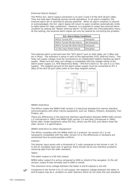
External Alarm Output<br />
The MX51x Ext. alarm output connection is on pins 3 and 4 of the AUX (8-pin) cable.<br />
They are held open (floating) during normal operations. In an alarm condition, the<br />
external alarm pin is switched to ground potential. When an alarm condition is cleared<br />
or acknowledged, the Ext. alarm signal will return to open condition automatically (refer<br />
to table below for relay conditions). However, it is possible to retain the external alarm<br />
condition by setting the “Retain external alarm:” to ON under the CFG1/Operation menu.<br />
At this setting, the external alarm signal can only be cleared by correcting the problem.<br />
Ext. Alarm Relay Conditions<br />
MX51x Turned OFF<br />
MX51x Turned ON (No Alarm)<br />
MX51x Turned ON (With Alarm)<br />
Energized<br />
Not Energized<br />
Energized<br />
12 VDC Input Power Failure Energized<br />
The external alarm is derived from the “EXT alarm” port on AUX cable, pin 3 (Blu) and<br />
pin 4 (Prpl). The software is setup in each of the appropriate CFG1 (Alarms) menu. The<br />
relay coil supply voltage must be connected to an independent battery backed-up alarm<br />
supply. Make sure the relay coil voltage is compatible with the voltage rating of the<br />
alarm power supply (i.e. NTE Electronics Relay - P/N R14-11D10-12 for use in a 12 VDC<br />
supply). The negative ground of the alarm power supply must be connected to Pin 3<br />
(Blu) of the AUX (8-pin) cable (refer to the relay diagram below).<br />
To a Battery Back-Up<br />
Alarm Power Supply<br />
- +<br />
MX 51X<br />
AUX (8-pin) Cable<br />
Pin 3 (Blue)<br />
AUX (8-pin) Cable<br />
Pin 4 (Purple)<br />
Coil<br />
Continuous-Duty<br />
SPDT Relay<br />
(12 VDC < 75 mA)<br />
N.C.<br />
C<br />
N.O.<br />
NMEA Interface<br />
The MX51x meets the NMEA 0183 version 2.3 electrical standard for marine interface<br />
communications with other marine equipment, such as: Radars, Plotters, Autopilots, Fish<br />
Finders, etc.<br />
There are differences in the electrical interface specification between NMEA 0183 version<br />
1.5 (introduced in 1987) and NMEA 0183 version 2.0 and later (introduced in 1994).<br />
Some older model equipment utilize RS-232, others use RS-422, and others meet the<br />
older version 1.5 specification.<br />
NMEA Interface to other Equipment<br />
The MX51x complies with the NMEA 0183 V2.3 protocol. As version V2.1 is not<br />
necessarily compatible with the older version V1.5, the differences in hardware are<br />
mentioned here to avoid possible conflicts:<br />
Listener:<br />
The listener input works with a threshold of 2 volts compared to the former 4 volt. It<br />
is still an insulated input and, in general, there should not be any interface problems<br />
receiving data from the older standard.<br />
Talker:<br />
The talker output is a RS-422 output:<br />
NMEA talker output B is active compared to GND or shield of the navigator. In the old<br />
version, output B was normally tied to GND or shield.<br />
The maximum drive voltage between the talker A and B outputs is ±6 volt.<br />
Compared to the former 0 to 15 volt output, the negative voltage between the talker A<br />
and B output may be a problem on older listeners which do not meet the new standard.<br />
104 | <strong>Installation</strong>