

a review - Acta Technica Corviniensis
a review - Acta Technica Corviniensis
a review - Acta Technica Corviniensis

You also want an ePaper? Increase the reach of your titles
YUMPU automatically turns print PDFs into web optimized ePapers that Google loves.
anchors then to the foundation. For Pre-stressed<br />
bridges, the problem is automatically solved due to<br />
the natural cambering of its girders. The expected<br />
constructional deflection will reduce the original<br />
cambering resulting in a flat surface under the effect<br />
of the total dead load of the bridge. {3} the prestressing<br />
force is placed eccentrically to counteract<br />
the downward deflection of the flexural member<br />
caused by gravity loads and service loads. The<br />
problem in steel bridges is more difficult, but it can<br />
be solved by fabricating an artificial cambering by an<br />
elaborate and costly methods. {4} not much has<br />
changed over the past thirty years in the general<br />
means and methods that a fabricator uses to induce<br />
camber in a member.{5} There is no known way to<br />
inspect beam camber after the beam is received in<br />
the field because of factors that include:<br />
The release of stress in member over time and in<br />
varying application.<br />
The effects of the dead weight of the member.<br />
The restraint caused by the end connections in the<br />
erected state.<br />
The effects of additional dead load that may<br />
ultimately be intended to be applied, if any.<br />
{5} AASHTO Specifications limits live load deflections<br />
to Span/800 for different types of ordinary bridges.<br />
But there is no specific limitation for dead load<br />
deflections. In the present research a test has been<br />
done to highlight the idea of a new suggested method<br />
for constructing the reinforced concrete deck slabs of<br />
Steel bridges. Temporary clamping of both ends of<br />
the supporting girders with adjacent panels girders -<br />
before casting the concrete of the reinforced<br />
concrete deck slab- can reduce mid span moment and<br />
deflection. It is believed that; the mentioned uncostly<br />
method can reduce construction deflections to<br />
acceptable limits.<br />
TESTING PROGRAM<br />
Materials: During all the test stages, the following<br />
materials have been used to simulate the following<br />
actual bridge components (presented in Table 1.)<br />
Table 1. Materials used<br />
Material Properties Simulation for<br />
Four steel rulers. Each ruler<br />
has the following properties:<br />
Cross sectional area of<br />
25x0.5 mm.<br />
Length of 30cm.<br />
1<br />
Weight of 1gm/cm.<br />
Bridge girders.<br />
Second moment of Area<br />
equals:<br />
2<br />
3<br />
98<br />
3<br />
3<br />
bh 25×<br />
0.5<br />
4<br />
( I ) = = = 0.26 mm<br />
12 12<br />
A number of 6 gm Plastic<br />
blocks having the dimensions<br />
of 6x20x40 mm.<br />
Super glue, Cyanoscrylete<br />
adhesive.<br />
4 Two Φ4mm bolts.<br />
5<br />
Eight, 35mm long, Erasing<br />
Rubbers having triangular<br />
cross sections.<br />
The weight of fresh<br />
concrete of a Bridge<br />
Deck- Slab.<br />
The role of Shear<br />
Connectors to join<br />
composite member<br />
components.<br />
Temporary End<br />
Clamping.<br />
Bridge Bearings.<br />
ACTA TECHNICA CORVINIENSIS – Bulletin of Engineering<br />
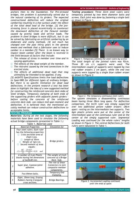
Testing procedure: Three 32cm steel rulers were<br />
temporary jointed by two 4mm diameter bolts and<br />
screws. Each joint was done by fastening a single bolt<br />
as shown in Figure 1.<br />
Figure 1. Temporary jointing the steel rulers by screws<br />
The total length of the jointed rulers was 92cm.<br />
Three 30 cm c/c supports were used. The<br />
intermediate couple of supports were topped by two<br />
red rubber erasers 2 cm apart, while the end two<br />
supports were topped by a single blue rubber eraser<br />
as shown in Figure 2.<br />
Figure 2. The temporary continuous steel rulers<br />
The system simulates a disassembling continuous<br />
beam having three 28cm long spans. For deflection<br />
comparison, the forth ruler was simply supported<br />
over two additional yellow rubber erasers -28cm<br />
apart –resting on the intermediate two supports. Two<br />
6gm plastic prisms were put at the center of the<br />
intermediate span of the continuous ruler and at the<br />
center of the simply supported ruler. Segmental<br />
Loading was continued for the whole rulers’ lengths<br />
as shown in Figure 3. The central Deflections for both<br />
rulers were tabulated in Table 1.<br />
Figure 3. Incremental Loading continued<br />
until the ends of spans<br />
2013. Fascicule 2 [April–June]


