ARM Processor Instruction Set
ARM Processor Instruction Set
ARM Processor Instruction Set
Create successful ePaper yourself
Turn your PDF publications into a flip-book with our unique Google optimized e-Paper software.
<strong>ARM</strong> <strong>Processor</strong> <strong>Instruction</strong> <strong>Set</strong><br />
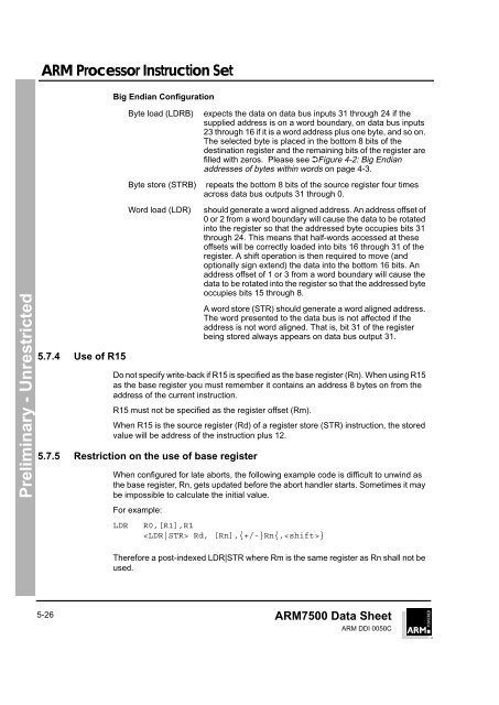
Big Endian Configuration<br />
Byte load (LDRB)<br />
expects the data on data bus inputs 31 through 24 if the<br />
supplied address is on a word boundary, on data bus inputs<br />
23 through 16 if it is a word address plus one byte, and so on.<br />
The selected byte is placed in the bottom 8 bits of the<br />
destination register and the remaining bits of the register are<br />
filled with zeros. Please see ➲Figure 4-2: Big Endian<br />
addresses of bytes within words on page 4-3.<br />
Byte store (STRB) repeats the bottom 8 bits of the source register four times<br />
across data bus outputs 31 through 0.<br />
Preliminary - Unrestricted<br />
5.7.4 Use of R15<br />
Word load (LDR)<br />
should generate a word aligned address. An address offset of<br />
0 or 2 from a word boundary will cause the data to be rotated<br />
into the register so that the addressed byte occupies bits 31<br />
through 24. This means that half-words accessed at these<br />
offsets will be correctly loaded into bits 16 through 31 of the<br />
register. A shift operation is then required to move (and<br />
optionally sign extend) the data into the bottom 16 bits. An<br />
address offset of 1 or 3 from a word boundary will cause the<br />
data to be rotated into the register so that the addressed byte<br />
occupies bits 15 through 8.<br />
A word store (STR) should generate a word aligned address.<br />
The word presented to the data bus is not affected if the<br />
address is not word aligned. That is, bit 31 of the register<br />
being stored always appears on data bus output 31.<br />
Do not specify write-back if R15 is specified as the base register (Rn). When using R15<br />
as the base register you must remember it contains an address 8 bytes on from the<br />
address of the current instruction.<br />
R15 must not be specified as the register offset (Rm).<br />
When R15 is the source register (Rd) of a register store (STR) instruction, the stored<br />
value will be address of the instruction plus 12.<br />
5.7.5 Restriction on the use of base register<br />
When configured for late aborts, the following example code is difficult to unwind as<br />
the base register, Rn, gets updated before the abort handler starts. Sometimes it may<br />
be impossible to calculate the initial value.<br />
For example:<br />
LDR<br />
R0,[R1],R1<br />
Rd, [Rn],{+/-}Rn{,}<br />
Therefore a post-indexed LDR|STR where Rm is the same register as Rn shall not be<br />
used.<br />
5-26<br />
<strong>ARM</strong>7500 Data Sheet<br />
<strong>ARM</strong> DDI 0050C


