iSTAR Pro 4U Rack Mount Quick Start Installation Guide
iSTAR Pro 4U Rack Mount Quick Start Installation Guide
iSTAR Pro 4U Rack Mount Quick Start Installation Guide

Create successful ePaper yourself
Turn your PDF publications into a flip-book with our unique Google optimized e-Paper software.
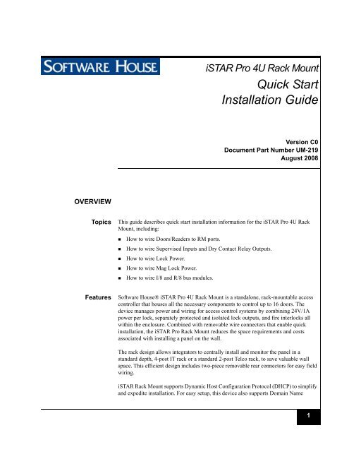
<strong>iSTAR</strong> <strong>Pro</strong> <strong>4U</strong> <strong>Rack</strong> <strong>Mount</strong><br />
<strong>Quick</strong> <strong>Start</strong><br />
<strong>Installation</strong> <strong>Guide</strong><br />
Version C0<br />
Document Part Number UM-219<br />
August 2008<br />
OVERVIEW<br />
Topics<br />
This guide describes quick start installation information for the <strong>iSTAR</strong> <strong>Pro</strong> <strong>4U</strong> <strong>Rack</strong><br />
<strong>Mount</strong>, including:<br />
• How to wire Doors/Readers to RM ports.<br />
• How to wire Supervised Inputs and Dry Contact Relay Outputs.<br />
• How to wire Lock Power.<br />
• How to wire Mag Lock Power.<br />
• How to wire I/8 and R/8 bus modules.<br />
Features<br />
Software House® <strong>iSTAR</strong> <strong>Pro</strong> <strong>4U</strong> <strong>Rack</strong> <strong>Mount</strong> is a standalone, rack-mountable access<br />
controller that houses all the necessary components to control up to 16 doors. The<br />
device manages power and wiring for access control systems by combining 24V/1A<br />
power per lock, separately protected and isolated lock outputs, and fire interlocks all<br />
within the enclosure. Combined with removable wire connectors that enable quick<br />
installation, the <strong>iSTAR</strong> <strong>Pro</strong> <strong>Rack</strong> <strong>Mount</strong> reduces the space requirements and costs<br />
associated with installing a panel on the wall.<br />
The rack design allows integrators to centrally install and monitor the panel in a<br />
standard depth, 4-post IT rack or a standard 2-post Telco rack, to save valuable wall<br />
space. This efficient design includes two-piece removable rear connectors for easy field<br />
wiring.<br />
<strong>iSTAR</strong> <strong>Rack</strong> <strong>Mount</strong> supports Dynamic Host Configuration <strong>Pro</strong>tocol (DHCP) to simplify<br />
and expedite installation. For easy setup, this device also supports Domain Name<br />
1
Features<br />
Services (DNS), Windows Internet Naming Service (WINS), and Fully Qualified<br />
Domain Naming (FQDN), thus providing a comprehensive approach to network<br />
management.<br />
A front panel LCD displays real-time system diagnostics and optional raw card reads<br />
for quick troubleshooting. LED status lights indicate power, fire alarm, fan failure, and<br />
high temperature. With external diagnostics and status lights, integrators and IT staff<br />
can view and handle system duress without having to open the enclosure. These security<br />
features significantly reduce the risk of system downtime and, with remote web<br />
diagnostics, you can find and fix performance issues remotely from anywhere in your<br />
facility.<br />
Each unit has front and rear tamper switches to ensure that the controller is not accessed<br />
by unauthorized personnel. Security risks are significantly reduced with encrypted<br />
communications, protection against network intrusion, dual network paths, and optional<br />
dial-up secondary communications. <strong>iSTAR</strong> <strong>Pro</strong> <strong>Rack</strong> <strong>Mount</strong> is a highly secure network<br />
device trusted by IT organizations.<br />
NOTE<br />
The unit supports RM readers and RM-4, 4E modules only - no direct Wiegand<br />
heads.<br />
FEATURES<br />
• Interfaces to 4-post IT rack or standard 2-post Telco rack<br />
• Includes everything required to control up to 16 doors, in one enclosure<br />
• Patent-pending design allows fast field wiring using quick connects<br />
• Front panel LCD and LEDs for diagnostics and quick troubleshooting<br />
• Includes lock power (12/24V, selectable), and separately-protected outputs<br />
• Industrial handles and slide rails ensure easy installation<br />
• Hinged cover for easy access to GCM diagnostic port<br />
• Dual network LAN ports for redundant network connection<br />
• Fully compatible with C•CURE® 800/8000 and C•CURE 9000<br />
• Supports multiple cards per cardholder and multiple card formats including FIPS<br />
201 extended formats<br />
• RM input/output modules allow expansion of up to 128 inputs and 128 outputs<br />
• Unit can be clustered and integrated with other <strong>iSTAR</strong> <strong>Pro</strong> controllers<br />
• Firmware is flashable<br />
2
Features<br />
System Components<br />
The <strong>iSTAR</strong> <strong>Pro</strong> <strong>4U</strong> <strong>Rack</strong> <strong>Mount</strong> hardware components consist of:<br />
Front Panel - With LCD to display the current status and for use when running<br />
diagnostics. Alarm Board provides Indicators for:<br />
<br />
<br />
<br />
<br />
Power<br />
Fire Alarm<br />
Fan Failure<br />
High Temp<br />
• Rear Connector Panel - Connectors for:<br />
<br />
<br />
<br />
<br />
8 or 16 door readers with Lock power<br />
16 or 32 Supervised Input connectors<br />
Two extra ports for I/8 and R/8 connections<br />
Fire Alarm input<br />
NOTE<br />
If you need to run additional wires through the rack enclosure, you can knock out<br />
the second LAN jack and use that opening for the cables – modem, battery<br />
connections, etc.<br />
• General Controller Module (GCM) – A general purpose board running Windows<br />
CE. The GCM has two PCMCIA slots for an internal modem, and/or a second<br />
network interface card and/or a compact flash card. There is a panel of NiMH<br />
batteries to retain the data memory in the event of a power failure.<br />
The <strong>iSTAR</strong> <strong>Pro</strong> GCM can interface with one or two ACM modules.<br />
• 1 or 2 Access Control Modules (ACM) – An access control board that<br />
communicates with the GCM and provides readers, outputs, and inputs. The <strong>iSTAR</strong><br />
<strong>Pro</strong> can have up to two ACMs that control 16 doors and provide connectors for up to<br />
16 RM readers or RM modules.<br />
• Front Panel Alarm board - Drive front panel indicators.<br />
• 1 or 2 APD8F-UL - Lock Power Distribution Boards.<br />
• 1 or 2 CPS1000-UL/CSA - 12/24 VDC (for APD8F-UL Lock Power Boards)<br />
• 1 CPS1000-UL/CSA-12 VDC Power Supply (for GCM, ACMs, Alarm Board, Fan)<br />
• 1 - Toroidal Transformer (30V 625VA).<br />
3
Features<br />
<strong>iSTAR</strong> <strong>Pro</strong> <strong>4U</strong> <strong>Rack</strong><br />
<strong>Mount</strong> Cabinet<br />
Fan<br />
Rails<br />
LCD Display<br />
Alarm Panel<br />
FIGURE 1. <strong>iSTAR</strong> <strong>Pro</strong> <strong>Rack</strong> <strong>Mount</strong> Enclosure<br />
<strong>Rack</strong> <strong>Mount</strong> Size and<br />
<strong>Rack</strong> Requirements<br />
• <strong>4U</strong> - 7" High<br />
• Standard 19" Wide<br />
• 29" Long to Shroud<br />
• 74 lbs Weight<br />
• A 32" Deep Server <strong>Rack</strong> is a Minimum Size Requirement.<br />
4
Features<br />
<strong>Mount</strong>ing Instructions,<br />
4 Post IT <strong>Rack</strong><br />
• Install <strong>Rack</strong> Rails to both sides of <strong>iSTAR</strong> <strong>Pro</strong> <strong>Rack</strong> enclosure. (Screws <strong>Pro</strong>vided)<br />
• Install <strong>Rack</strong> Rails to Server <strong>Rack</strong>.<br />
• Slide <strong>iSTAR</strong> <strong>Pro</strong> into <strong>Rack</strong> Rails on Server <strong>Rack</strong><br />
• Attach <strong>iSTAR</strong> to Server <strong>Rack</strong> for added Security<br />
<strong>Mount</strong>ing Instructions,<br />
2 Post Telco <strong>Rack</strong><br />
The <strong>4U</strong> <strong>Rack</strong> <strong>Mount</strong> can also be mounted in a 2 Post Telco style rack by using a 2 post<br />
conversion kit.<br />
• Install <strong>Rack</strong> Rails to both sides of <strong>iSTAR</strong> <strong>Pro</strong> <strong>Rack</strong> enclosure. (Screws <strong>Pro</strong>vided)<br />
• Install 2 post conversion kit<br />
• Install rack rails onto metal extensions of the conversion kit<br />
• Slide <strong>iSTAR</strong> <strong>Pro</strong> onto the rails of the conversion kit<br />
• Attach <strong>iSTAR</strong> to Server <strong>Rack</strong> for added Security<br />
Network Connection • Connect a CAT-5 or CAT-6 RJ45 cable to J4. Connect a straight through cable to a<br />
Switch or Hub. If unit is connected directly to the server use a crossover cable.<br />
• GCM LED2 indicates the Ethernet link signal and LED1 displays the Receive Data<br />
signal.<br />
5
Features<br />
<strong>iSTAR</strong> <strong>Pro</strong> <strong>4U</strong> <strong>Rack</strong> <strong>Mount</strong> Layout<br />
FIGURE 2. <strong>4U</strong> <strong>Rack</strong> <strong>Mount</strong> Layout<br />
6
Features<br />
Part Numbers<br />
TABLE 1. <strong>iSTAR</strong> <strong>Pro</strong> <strong>4U</strong> <strong>Rack</strong> <strong>Mount</strong> Main Components<br />
Part Number<br />
Description<br />
STAR016-<strong>4U</strong>RM<br />
STAR008-<strong>4U</strong>RM<br />
<strong>4U</strong> <strong>iSTAR</strong> <strong>Pro</strong> <strong>Rack</strong> <strong>Mount</strong>, 16 reader with integral lock<br />
power, supports RM devices only (no direct Wiegand)<br />
<strong>4U</strong> <strong>iSTAR</strong> <strong>Pro</strong> <strong>Rack</strong> <strong>Mount</strong>, eight reader with integral lock<br />
power, supports RM devices only (no direct Wiegand)<br />
TABLE 2. Boards/Spares<br />
Tyco Part Number Mfg. p/n, if different Description<br />
0311-0068-01 <strong>iSTAR</strong> <strong>Pro</strong> GCM Board<br />
0311-0040-01 <strong>iSTAR</strong> <strong>Pro</strong> ACM Board<br />
4828-0025-01 Blue LCD<br />
DISP,LCD,16CX2L,BK-LT,BL,84X44<br />
5606-0068-01 AlarmSaf CPS1000-UL/CSA 12/24V Power Supply, 10A<br />
5606-0069-01 AlarmSaf APD8-BD 8-output Pwr. Dist. Board<br />
5610-0013 120/30 Toroidal Xfmr<br />
IB-100-B<br />
Front Alarm PCA<br />
7
Specifications<br />
SPECIFICATIONS<br />
Following are specifications for the <strong>iSTAR</strong> <strong>Pro</strong> <strong>4U</strong> <strong>Rack</strong> <strong>Mount</strong>:<br />
TABLE 3. Physical Specifications<br />
Physical<br />
Dimensions (H x W x D)<br />
Space Requirements<br />
Environmental<br />
Weight<br />
Misc. Alarms<br />
Temperature Alarm<br />
18 x 48 x 74 cm<br />
(7 x 19 x 29 in)<br />
<strong>4U</strong> (standard rack units)<br />
0° to 50° C (32° to 122° F),<br />
5 to 95% relative humidity, non-condensing<br />
34 kg (74 lbs)<br />
Fan failure, High temperature<br />
60° +/- 6°C, (140° +/- 10°F)<br />
TABLE 4. Electrical Specifications<br />
Electrical<br />
Power Requirements<br />
Power (Typical/Max/Min)<br />
Heat Dissipation (Typical)<br />
AC Input Circuit Breaker Rating<br />
UPS Operation<br />
Memory and RTC Backup<br />
Max Lock Power (Total Output)<br />
115 VAC, 60 Hz<br />
75W/300W/50W<br />
500 BTU/h<br />
5A<br />
Battery charging included, with optional<br />
17Ah batteries (5) provides nominal four hours<br />
backup time; 48 hour recharge time<br />
On-board rechargeable NimH batteries provide<br />
minimum 12 hours retention of RAM and RTC (Real<br />
Time Clock)<br />
16A<br />
Individual Lock Current Limit 2.5A<br />
Lock Relay Ratings<br />
250,000 cycles<br />
8
Specifications<br />
TABLE 5. Electrical Specifications<br />
Indicators and Switches<br />
LED for power, high temp, fire, fan<br />
failure<br />
LCD for diagnostics<br />
Notes<br />
Relay outupts are available for tie-in to spare<br />
inputs.<br />
See “GCM Diagnostic Display Selections”<br />
on page 37.<br />
TABLE 6. Communication to Doors<br />
Communication to<br />
Doors<br />
Communications Bus<br />
Communications Type<br />
Maximum Distance to Door<br />
RM bus, separate run to each door<br />
RS-485 half duplex, two-wire, plus optional two<br />
wires for reader power<br />
1,219 m (4,000 ft.)<br />
9
Specifications<br />
TABLE 7. Readers, Inputs, and Outputs<br />
Readers, Inputs, and<br />
Outputs<br />
Reader Ports 16<br />
Reader Support<br />
RM readers or RM reader modules<br />
Reader Technologies Supported • Multi-Technology<br />
• <strong>Pro</strong>ximity<br />
• Smart Card<br />
• Wiegand<br />
• Magnetic Stripe<br />
• HID iCLASS<br />
Supervised Inputs<br />
Outputs<br />
Output <strong>Pro</strong>tection<br />
Fire Alarm Interlock<br />
Tamper Switches<br />
32, double 1 K ohm resistors<br />
16, 1A nominal (max 2.5A)<br />
24 VDC lock power per output<br />
Class 2 power limited dry contact operation,<br />
selectable per output.<br />
Individually fused with<br />
resettable PTC fuses<br />
Per lock output, individually settable via<br />
jumpers<br />
Two, front and rear cover<br />
TABLE 8. Regulatory Specifications<br />
Regulatory<br />
Tested and certified by ETL per ANSUI/UL standard 294-2004 FCC Part 15 Class B.<br />
10
COMPONENTS/<br />
CONNECTIONS<br />
Front Panel<br />
The front panel is shown in Figure 3. It provides the LCD panel for status and<br />
diagnostics. There are also indicators for:<br />
• Power<br />
• Fire Alarm<br />
• Fan Failure<br />
• High Temperature<br />
FIGURE 3. Front Panel<br />
11
Components/Connections<br />
Alarm Board<br />
The Alarm board is mounted just behind the alarm indicators. The layout of the Alarm<br />
board is shown in Figure 4.<br />
Fan Power Out<br />
+12VDC In<br />
Fire Alarm In<br />
(from rear panel)<br />
Supervision Resistors<br />
Alarm Outputs<br />
for Alarm outputs<br />
(connect to inputs on ACM, if desired)<br />
FIGURE 4. Alarm Board Layout<br />
Connect Front Panel Alarms to Inputs<br />
The Fire Alarm, Fan Failure, and Over Temperature alarms can be wired to ACM inputs<br />
and used to create events in the C•CURE system. The alarms are supervised as NC<br />
inputs on the Alarm board.<br />
Steps to monitor the alarms:<br />
1. Select unused inputs on an ACM.<br />
2. Remove the wires that go to the rear connection panel from the selected input<br />
connector.<br />
3. Wire each pair of pins on Alarm Board J1 to the selected input connector.<br />
4. Configure the inputs and events in the C•CURE system.<br />
12
Components/Connections<br />
Rear Connection Panel<br />
Power Input<br />
On/Off Switch<br />
Circuit Breaker<br />
2 RM Ports<br />
Network Connection<br />
16 Doors<br />
with Lock Power<br />
(8 per ACM)<br />
32 Inputs<br />
(16 per ACM)<br />
Fire Alarm (NO)<br />
FIGURE 5. Rear Connection Panel<br />
13
Components/Connections<br />
Top Row Rear Connectors<br />
Figure 6 and Figure 7 show details of the rear connectors.<br />
The door connectors provide +12 VDC, Data+, Data-, and GND for the RM-4 or RM-<br />
4E. Doors 1-8 are mapped to doors 1-8 of the first ACM. Doors 9-16 are mapped to<br />
doors 1-8 of the second ACM.<br />
The Lock outputs can be sourced with 24VDC or 12VDC for lock power or other output<br />
devices. The Lock outputs can also be set as Dry Contacts and used with external power<br />
for the locks or can be used as ordinary outputs. There is also a grounded pin to connect<br />
the shield of the cables.<br />
The inputs are ordinary Software House supervised inputs that can be wired as NO or<br />
NC. Each pair is wired to an input on the ACMs. Inputs 1-16 are mapped to inputs 1-16<br />
of the first ACM. Inputs 17-32 are mapped to inputs 1-16 of the second ACM.<br />
FIGURE 6. Top Row Rear Connectors - <strong>4U</strong> RM <strong>Rack</strong> <strong>Mount</strong> ISTAR<br />
14
Components/Connections<br />
Bottom Row Rear Connectors<br />
Doors 9-16 and Inputs 21-32 are on the bottom connector.<br />
The Fire Alarm input (FA/NO) on the IN31-32 connector is a Normally Open (NO) dry<br />
connection. When the connection closes, it indicates an external Fire Alarm is active. If<br />
an APD8 jumper is set to position D, the lock power for that lock will be inhibited. See<br />
Figure 19 for more details. The Fire Alarm will also be indicated on the front panel and<br />
can be wired to an input and used to create an event in the C•CURE system. See page12.<br />
Tied to Door 8<br />
on ACM 1<br />
Tied to Door 16<br />
on ACM 2<br />
Set ACM S1-1 to OFF<br />
when RM8/16 are used<br />
FIGURE 7. Bottom Row Rear Connectors - <strong>4U</strong> RM <strong>Rack</strong> <strong>Mount</strong> ISTAR<br />
Adding I/8 or R/8 Bus Modules<br />
It is possible to wire bus modules on the same lines as Doors 1-16, observing normal<br />
RS-485 termination rules.<br />
Another option is to use the RM BUS connector. The RM BUS connector has two RM<br />
Bus connections which can be used to wire I/8 and R/8 bus modules.<br />
RM 8 and DR 8 are connected to STAR1 on the first ACM. RM 16 and DR 16 are<br />
connected to STAR1 on the second ACM.<br />
15
Components/Connections<br />
If you want to use RM 8 or RM 16, set S1 position 1 to OFF (No Termination) on that<br />
ACM. See Figure 8.<br />
NOTE<br />
The total length of the half duplex RS-485 connection is 4000 feet.<br />
S1-1=ON<br />
S1-1=OFF<br />
FIGURE 8. RM Terminations<br />
16
Components/Connections<br />
After wiring the connections to the rear panel, use the shroud to protect the cables and<br />
provide enough of a service loop to allow the rack mount to be pulled out from the front.<br />
Strain relief<br />
fitting,<br />
attached to<br />
<strong>iSTAR</strong> to<br />
help prevent<br />
connectors<br />
from pulling<br />
loose.<br />
FIGURE 9. Wires from Rear of <strong>Rack</strong> <strong>Mount</strong><br />
17
Components/Connections<br />
Power Supplies<br />
There are three power supplies included with the <strong>4U</strong> <strong>Rack</strong> <strong>Mount</strong> <strong>iSTAR</strong> <strong>Pro</strong>. The<br />
supplies are all CPS-1000 units that provide 10 Amps each. For clarity, we will refer to<br />
them as units 1, 2, and 3.<br />
• Unit 1 - Factory set to +12 VDC. Do not change. This unit supplies the various logic<br />
boards.<br />
• Unit 2 - Set for + 24 VDC by default. Can be changed to +12 VDC. This unit<br />
supplies the APD8 for doors 9-16. The APD8 board for doors 9-16 is mounted on<br />
top, above the APD8 1-8 board.<br />
• Unit 3 - Factory set for + 24 VDC. Do not change. This unit supplies the APD8 for<br />
doors 1-8 and the Fire Alarm detection logic. The APD8 board for doors 1-8 is<br />
mounted on the bottom, below the APD8 9-16 board.<br />
+24 VDC<br />
for APD8 1-8<br />
+24 or +12 VDC<br />
for APD8 9-16<br />
+12 VDC Power for GCM, ACMs,<br />
Alarm Board and Fan<br />
3<br />
2<br />
1<br />
FIGURE 10. Power Supplies<br />
18
Components/Connections<br />
AC IN Indicator<br />
DC1 Output Voltage present<br />
Not Used<br />
30 VAC IN<br />
Voltage OUT<br />
+24 VDC or<br />
+12 VDC<br />
15 A Fuse<br />
Battery Charge<br />
OUT<br />
Not Used<br />
J1<br />
Do not change S1<br />
AC and DC<br />
Fault relays can<br />
be wired to ACM<br />
inputs.<br />
Jumpers J3, J1<br />
Both in = +12 VDC<br />
Both out = +24 VDC<br />
DC OUT Indicator<br />
Regulator output voltage<br />
within tolerance<br />
FIGURE 11. CPS-1000 Detail<br />
Battery Backup<br />
Usually the <strong>4U</strong> <strong>iSTAR</strong>s are mounted in racks with power from a Liebert UPS or similar<br />
device, so batteries are not needed. However, if needed, the three power supplies in the<br />
<strong>4U</strong> can also charge batteries.<br />
Connect the battery(s) as shown in Figure 12. Be sure to observe polarity.<br />
19
Components/Connections<br />
FIGURE 12. Battery Connections<br />
Backup Time<br />
To calculate the actual backup time you need to estimate the total current draw per<br />
power supply, and provide batteries attached to each power supply.<br />
Here is a rough worst case estimate:<br />
• Mag locks – draw 400mA all the time, so 8 locks x .40A = 3.2A<br />
• 17AHr batteries will give you about 5 hrs (17AHr/4A) at 3.2A.<br />
• So you’ll need one battery for 12V locks, and two batteries for 24V locks.<br />
Using 24V locks<br />
• Using 24 V locks, you would need 5 17AHr batteries for the whole unit – 2 for each<br />
of the two lock power supplies, and one for the board power supply (which is set to<br />
12V).<br />
• You need a battery shelf in the rack.<br />
Note – the CPS 1000 power supplies need 48 hours recharge time for 17AHr batteries.<br />
Power Supply Troubleshooting<br />
FIGURE 13. Power Supply Troubleshooting<br />
20
Components/Connections<br />
APD8 Boards<br />
AlarmSaf boards APD8<br />
Figure 14 shows how the power supply is wired to the APD8 board.<br />
FIGURE 14. AlarmSaf APD8<br />
The APD8 is an access control power distribution system providing eight relay<br />
controlled, individually protected outputs. The APD8 provides Class-2 power limited<br />
outputs via PTC protection. The board can be operated from 12V or 24V AC or DC and<br />
features independently programmable outputs, Fire Alarm Interface and visual status<br />
indication.<br />
• Eight outputs - each individually programmable for form-C dry contact, continuous<br />
output voltage, and FAI controlled<br />
• Eight inputs - each individually wired from ACM relay outputs<br />
• Fire Alarm Interface<br />
• Class-2 Power Limited outputs<br />
• Visual status indication<br />
• Input Activation (Red LED)<br />
• Control Voltage Present (Green LED)<br />
• FAI Status (Green LED OFF)<br />
• Removable field wiring terminal strips<br />
21
Components/Connections<br />
Input from ACM Relay<br />
CDX Jumpers for<br />
Output Mode<br />
DIP Switch set for Negative Trip<br />
Do not change<br />
Power Source<br />
is present<br />
Power Jumpers<br />
Do not change<br />
Door Outputs<br />
NO = Relay NO<br />
C = Relay Common<br />
NC = Relay NC<br />
COM = Voltage Common<br />
LED indicating<br />
Output is active<br />
LED indicating no<br />
F/A when lit<br />
Power IN<br />
FIGURE 15. APD8 Layout<br />
22
Components/Connections<br />
FIGURE 16. CDX Jumper<br />
TABLE 9. Troubleshooting<br />
Condition Possible Cause Solution<br />
No power on output(s)<br />
Output not dropping power<br />
on a FA input<br />
J1 and J2 set incorrectly<br />
No power input<br />
Zone Input in the wrong state<br />
Zone Output wired incorrectly<br />
Output Configuration Jumper set<br />
incorrectly<br />
Blown Fuse / Tripped PTC<br />
FACP Input active<br />
Other <strong>Pro</strong>blem<br />
Output Configuration Jumper set<br />
incorrectly<br />
FACP Input wired incorrectly<br />
Zone Output wired incorrectly<br />
Both jumpers should be in.<br />
Verify power is present on the power input terminals.<br />
If J1 and J2 are removed, BOTH power<br />
inputs must be powered.<br />
Verify the input is configured properly<br />
Verify the output is configured properly<br />
See Figure 16<br />
Verify output integrity and replace fuse, or<br />
remove output load to reset PTC.<br />
Verify that the FACP input is not activated.<br />
Contact AlarmSaf<br />
See Figure 16<br />
Verify the FACP Input configuration<br />
Verify the Zone Output wiring<br />
23
Components/Connections<br />
Interconnections<br />
Lock Varieties<br />
RM4 to Head End Wiring Instructions<br />
Reader Diagram<br />
1. Connect RM Power (Red) to pin 1<br />
2. Connect Data + (White) to pin 2<br />
3. Connect Data - (Green) to pin 3<br />
4. Connect RM GND (Black) to pin 4<br />
5. Connect the shield to pin 6<br />
Figure 17 shows the wiring connections for an RM reader connector.<br />
FIGURE 17. RM Door Snap-In Connector<br />
24
Components/Connections<br />
Lock Power Variations<br />
Normal Default Case (RM readers with wet sourced power)<br />
1. Verify the JPn jumper to be in the C position.<br />
2. Connect Lock+ to pin 9<br />
3. Connect Lock- to pin 10<br />
FIGURE 18. Sourced Lock Power<br />
25
Components/Connections<br />
Default Sourced Wet with F/A<br />
RM readers with sourced wet power gated by F/A<br />
1. Wire the NO Fire Alarm (F/A) to the rear connector panel.<br />
2. Verify the JPn jumper to be in the D position.<br />
3. Connect Lock+ to pin 9<br />
4. Connect Lock- to pin 10<br />
When the F/A NO signal is true (shorted), all lock outputs that are in the D position will<br />
have the lock power inhibited.<br />
FIGURE 19. Lock Power - Fire Alarm Option<br />
26
Components/Connections<br />
Maglock<br />
RM Readers with Mag Locks<br />
Maglocks require a normally energized output.<br />
1. Verify the JPn jumper to be in the either the C or D position<br />
2. Move the wire from the NO pin to the NC pin<br />
3. Connect Lock+ to pin 9<br />
4. Connect Lock- to pin 10<br />
It is also possible to accomplish the normally energized case by other means:<br />
• Move the NO wire on the ACM relay to the NC pin.<br />
• <strong>Pro</strong>gram the output to be normally energized in the software of the C•CURE system<br />
FIGURE 20. Mag Lock<br />
27
Components/Connections<br />
Dry Contact<br />
RM Readers with dry power<br />
The dry contact method requires an external power supply<br />
1. Verify the JPn jumper to be in the either the X position<br />
2. Move the wire from the COM pin to the C pin<br />
3. Connect one side of the lock to pin 9. (Observe polarity)<br />
4. Connect one side of the power source to pin 10. (Observe polarity)<br />
5. Connect the other side of the power source to the other side of the lock. (Observe<br />
polarity)<br />
FIGURE 21. Dry Contact<br />
28
Components/Connections<br />
Fail Safe/Fail Secure<br />
The following two examples show an electric strike wired as both Fail Secure and Fail<br />
Safe.<br />
Fail Secure Wiring<br />
Fail Safe Wiring<br />
Use the C•CURE Administration application to configure the output as Normally<br />
Energized for the Fail Safe case.<br />
29
Cable Distances and Power<br />
CABLE DISTANCES<br />
AND POWER<br />
Following are maximum cable distances when supplying power to RM-4 and RM-4E<br />
Readers from the <strong>4U</strong> <strong>Rack</strong> <strong>Mount</strong>.<br />
RM-4 Readers<br />
TABLE 10. Power for RM-4<br />
Power from<br />
Door<br />
Connectors to<br />
RM-4<br />
Wire Size<br />
Max cable<br />
distance (ft.) for<br />
RM-4 Only<br />
Max cable<br />
distance (ft.) for<br />
RM-4 with LCD<br />
Max cable<br />
distance (ft.) for<br />
RM-4 with LCD<br />
and Read Head<br />
24 AWG 690 390 300<br />
22 AWG 1095 620 470<br />
20 AWG 1740 985 740<br />
18 AWG 2765 1565 1200<br />
RM-4E Readers<br />
TABLE 11. Power for RM-4E<br />
Power from<br />
Door<br />
Connectors to<br />
RM-4E<br />
Wire Size<br />
Max cable<br />
distance (ft.) for<br />
RM-4E only<br />
Max cable<br />
distance (ft.) for<br />
RM-4E with LCD<br />
Max cable<br />
distance (ft.) for<br />
RM-4E with LCD<br />
and Read Head<br />
24 AWG 800 350 150<br />
22 AWG 1270 560 240<br />
20 AWG 2015 890 380<br />
18 AWG 3200 1410 600<br />
TABLE 12. Wire Size and Ohms Per Foot<br />
Wire Size<br />
Ohms per Foot<br />
24 AWG 0.02567<br />
22 AWG 0.01614<br />
20 AWG 0.01015<br />
18 AWG 0.00639<br />
30
Cable Distances and Power<br />
Following are maximum cable distances when supplying power to I/8 and R/8 bus<br />
modules from the <strong>4U</strong> <strong>Rack</strong> <strong>Mount</strong>..<br />
I/8 - R/8 Bus Modules<br />
TABLE 13. Power for I/8 and R/8<br />
Power from RM<br />
Connectors to<br />
I/8 or R/8 Wire Size<br />
Max cable<br />
distance (ft.) for<br />
I/8<br />
Max cable<br />
distance (ft.) for<br />
R/8. (With all 8<br />
relays active)<br />
24 AWG 390 225<br />
22 AWG 620 350<br />
20 AWG 985 560<br />
18 AWG 1565 900<br />
31
Cable Distances and Power<br />
Inputs<br />
Input Diagram<br />
Figure 22 shows the wiring diagram of an input connector<br />
FIGURE 22. Input Connector<br />
32
Cable Distances and Power<br />
NO and NC Input<br />
Inputs<br />
The wiring of supervised inputs is shown in the next two figures. Note that the resistor<br />
network is different for NO and NC switches.<br />
Normally Open (NO) Wiring<br />
Normally Closed (NC) Wiring<br />
NOTE<br />
To comply with UL requirements, use shielded, minimum 22 AWG stranded,<br />
twisted pair cable for monitor points, DSMs, and REXs. Use Belden 9462 or<br />
equivalent.<br />
33
Cable Distances and Power<br />
GCM Board<br />
GCM Module<br />
FIGURE 23. GCM Module<br />
34
GCM General Control Module<br />
GCM GENERAL<br />
CONTROL MODULE<br />
Figure 24 shows the GCM components described in this guide.<br />
FIGURE 24. CGM Control Module Layout<br />
35
GCM General Control Module<br />
Network Connection<br />
Connect a CAT 5 RJ45 cable to the primary LAN port on the rear of the unit.. If the<br />
other end of the cable is connected to a hub or switch, it must be straight through. If it is<br />
connected directly to a NIC card on the server, the cable must be a crossover.<br />
LED2 indicates the Ethernet Link signal and LED1 displays the Receive Data signal.<br />
Dual Network Connection<br />
If a dual network connection is required, perform the following steps:<br />
1. Install a STAR-PCC-NIC card in one of the PCMCIA slots.<br />
2. Run a straight through CAT-5 RJ-45 patch cable from the inside of the second RJ-45<br />
connector to the PCMCIA card.<br />
3. Connect both RJ-45 connectors on the rear panel to network connections.<br />
LEDs<br />
LED4 – indicates power and shines through an opening in the door.<br />
LED2 – displays the Ethernet Link signal on P6.<br />
LED1 – displays the Receive Data signal on P6.<br />
LCD Panel<br />
The LCD panel will display various status information, such as the connection status to<br />
the host, and various diagnostic functions.<br />
If the LCD panel is difficult to read, adjust the contrast using the potentiometer at the<br />
upper right section of the GCM.<br />
36
GCM General Control Module<br />
GCM Diagnostic Display Selections<br />
S4 - Diagnostic Features and Status Messages<br />
S4 positions 5 through 8:<br />
• Activate status messages (with ICU Block on or off)<br />
• Activate diagnostic tests for troubleshooting<br />
• Disable DIMM slot memory burst mode<br />
TABLE 14. S4 Switch Settings for Diagnostic and Status Messages<br />
S4 Switch Setting<br />
Description<br />
S4-5 S4-6 S4-7 S4-8<br />
Off Off Off Off ICU Block Off (Read/Write/Update) - Display General Messages<br />
On On On On ICU Block On (Read only) - Display General Messages<br />
Off Off Off On Display card data from last card read (slow mode).<br />
Off On Off On Display card data from last card read (fast mode).<br />
Off Off On Off Display supervised input changes, 2 second LCD display.<br />
Off On On Off Display supervised input changes, 1 second LCD display.<br />
Off Off On On Manual output test (including readers and R/8 boards).<br />
Off On Off Off Automatic ACM output test (does not include readers and R/8 boards).<br />
Off On On On Automatic ACM output test (including readers and R/8 boards).<br />
On Off Off Off Test Ethernet/PCMCIA ports and devices.<br />
On On Off Off Test DIMM memory<br />
On Off Off On Test battery charger.<br />
On Off On On Disable DIMM slot memory burst mode. You must disable burst mode<br />
if you are not using a supported DIMM and cannot boot the <strong>iSTAR</strong> <strong>Pro</strong> or<br />
you are receiving boot errors. After disabling burst mode, the <strong>iSTAR</strong> <strong>Pro</strong><br />
will boot normally.<br />
After booting the <strong>iSTAR</strong> <strong>Pro</strong>, you can set S4-5 through S4-8 to other<br />
positions as needed. If the memory does not work in burst mode, disable<br />
burst mode when you boot the <strong>iSTAR</strong> <strong>Pro</strong>.<br />
37
GCM General Control Module<br />
S4 Restricted Switches<br />
S4 positions 1 through 4:<br />
• Are reserved for <strong>iSTAR</strong> <strong>Pro</strong> features<br />
• Activate diagnostic or repair operations for use by Technical Support<br />
representatives.<br />
TABLE 15. S4 Restricted Switches<br />
Switch Setting<br />
Position 1 Position 2 Position 3 Position 4<br />
Description<br />
On On or Off On or Off On or Off Reserved. Do not set position 1 to Off unless specifically<br />
instructed to do so by Customer Support.<br />
Off Off Off Off Normal operation.<br />
Off On Off Off Clears on board DIMM memory and data on flash memory.<br />
Note:<br />
This switch resets the <strong>iSTAR</strong> <strong>Pro</strong> to the factory<br />
default. You must reconfigure the IP address and<br />
identity parameters if you use these settings.<br />
Off Off On Off Reserved. Do not use these combinations.<br />
Off Off On On<br />
Off On Off On<br />
Off On On Off<br />
Off On On On<br />
Off Off Off On Causes <strong>iSTAR</strong> <strong>Pro</strong> to reboot using the boot image instead of<br />
the main image.<br />
MAC Address<br />
When configuring an <strong>iSTAR</strong> Controller, it is necessary to supply the MAC address of<br />
the NIC card that is connected.<br />
The MAC address for the on-board 10BaseT NIC is displayed on a sticker just left of<br />
the Power LED.<br />
If a PCMCIA NIC card is used, the MAC address will be provided by the manufacturer.<br />
38
GCM General Control Module<br />
GCM Batteries<br />
Use NiMH (Nickel Metal Hydride) batteries - AA size..Minimum 2400 milli-amp<br />
hours.<br />
Software House recommends that you replace the NiMH (Nickel Metal Hydride) AA<br />
size batteries yearly.<br />
Caution: Risk of explosion if battery is replaced by an incorrect type. Dispose of<br />
used batteries according to the instructions.<br />
<strong>iSTAR</strong> <strong>Pro</strong> batteries are packaged separately and should be installed in the battery<br />
backup sockets at the bottom of the GCM.<br />
The unit is stored and shipped with the batteries disconnected so they will not be<br />
drained while in storage. Connect the batteries as shown in the GCM diagram that<br />
follows. If the batteries are installed with the power off, the reset switch (S5) must be<br />
pressed after power is applied.<br />
It is acceptable to install the batteries with the power on. However, if the batteries are<br />
installed with the power on, you do not need to press the reset switch.<br />
NOTE<br />
The batteries provide power to retain the volatile memory (clearances, activity,<br />
etc.) data in the event of a power failure. The batteries do not supply enough<br />
power for <strong>iSTAR</strong> <strong>Pro</strong> normal operations.<br />
Diagnostic Session<br />
A diagnostic session can be run either through ICU or with a terminal session through<br />
P5. Turn on the diagnostic information settings using either ICU or the HTTP<br />
connection to the <strong>iSTAR</strong> <strong>Pro</strong>.<br />
NOTE<br />
The diagnostic information causes overhead and should not be activated during<br />
normal operation.<br />
1. Connect P5 to a COM port on a PC.<br />
Use a straight through DB9F to DB9F cable.<br />
2. Set the COM port to 115,200 baud, 8 data bits, None, 1 stop bit, Hardware Flow<br />
Control.<br />
3. <strong>Start</strong> a terminal session using an emulator such as HyperTerminal.<br />
Dip Switches • DIP Switch S2 is factory set for RS232 on P6. Do Not Change.<br />
• DIP Switch S1 is factory set for RS232 on P6. Do Not Change.<br />
• DIP Switch S4 is used to control diagnostics, clear memory, and to display card<br />
reads in hexadecimal.<br />
To display card reads in hexadecimal on the LCD panel, set switch 4-8 On. The data that<br />
is displayed is left-justified. There may be some unused bits on the right side of the<br />
display.<br />
39
GCM General Control Module<br />
The Reset Switch, S5, will cause the GCM computer to reboot. Pressing S5 will also<br />
clear memory, including configured readers, inputs and outputs. As long as there is a<br />
connection to the host, these objects will immediately be downloaded to the <strong>iSTAR</strong> <strong>Pro</strong><br />
memory.<br />
If switch S4-2 is on when S5 is pressed, the unit will be reset to factory default. This<br />
means that all of the connection data, such as the IP address will be cleared in addition<br />
to the memory. In this case the unit will have to be totally configured again using<br />
ICU.exe.<br />
40
ACM - Access Control Module(s)<br />
ACM - ACCESS<br />
CONTROL<br />
MODULE(S)<br />
The ACM (Access Control Module) provides the Readers, Inputs and Outputs that are<br />
used in access control. An <strong>iSTAR</strong> <strong>Pro</strong> can contain either one or two ACMs.<br />
ACM Module<br />
FIGURE 25. Photograph of <strong>iSTAR</strong> <strong>Pro</strong> ACM<br />
FIGURE 26. ACM Access Control Module Layout<br />
41
ACM - Access Control Module(s)<br />
RM4 Readers<br />
Either Wiegand signaling or Magnetic signaling read heads are connected to RM-4s or<br />
RM-4Es. The RM-4 or RM-4E readers are interfaced through the rear connector panel.<br />
The signals are wired internally to the STAR1 through STAR8 connectors on the ACM.<br />
Pin 1 for each connector is shown in the preceding diagram. It is important that the ports<br />
are wired as follows:<br />
TABLE 16. Pin Signals and Colors<br />
STARx Pin Signal Color<br />
1 +12 VDC Red<br />
2 Tx+ / Rx+ White<br />
3 Tx- / Rx- Green<br />
4 GND Black<br />
The STARn connectors are not keyed so it is possible to reverse the signals. If the<br />
ground connector (pin 4) is connected to +12 VDC (pin 1), damage to the power supply<br />
or the RM could result.<br />
The reader number is determined by a hexadecimal switch on the RM, not by the Port<br />
into which the reader is plugged. To enable the correct reader number, set the<br />
appropriate S2-n hexadecimal switch ON. For example, S2-1 is for reader 1, S2-2 is for<br />
reader 2, etc.<br />
S4 is used to terminate the two wire, half duplex RS485 signals at the <strong>iSTAR</strong>. Note that<br />
the S4 switch is mounted upside down in the normal front view. This is done so that<br />
switch 1 is on the right and switch 8 is on the left, and the switches have the same<br />
orientation as the ports.<br />
NOTE<br />
The rear connector doors are wired numerically in reverse. Door1 is wired to<br />
STAR8 and Door2 is wired to STAR7, etc. The actual reader number is defined by<br />
the Hex switch in the RM module.<br />
42
ACM - Access Control Module(s)<br />
LEDs<br />
TABLE 17. ACM LEDs<br />
LED<br />
DS3<br />
DS1<br />
DS2<br />
DS4 - DS11<br />
Function<br />
Indicates power to the ACM.<br />
Indicates Rx on the RS485 half duplex reader bus.<br />
Indicates Tx on the RS485 half duplex reader bus.<br />
Displays the eight outputs on the ACM.<br />
NOTE<br />
DS1 and DS2 should be on solid. If they are blinking, it indicates that something<br />
(e.g., Reader, I/8, R/8, etc.) is configured in the software but is not seen by the<br />
hardware. This may or not be a hardware failure, depending on the intent of the<br />
technician. (i.e., It is possible to configure hardware before actually installing it.)<br />
If DS1 and DS2 are blinking, it causes some overhead to the <strong>iSTAR</strong>.<br />
Switches<br />
TABLE 18. ACM Switch Functions<br />
Switch Function Description<br />
S5 Reset Switch Resets the <strong>iSTAR</strong> ACM<br />
S2<br />
S4<br />
S3<br />
Enable Wiegand<br />
Ports<br />
Terminate the RM<br />
RS485 Ports<br />
(STAR1-STAR8)<br />
LED and Beep<br />
Control<br />
Do Not Use<br />
These switches default to ON and generally<br />
should not be changed. Setting the switch to<br />
OFF places the STARn port in the middle of<br />
the RS485 chain, which allows the technician<br />
to connect two sections of a reader bus to this<br />
point. In this case, termination must be<br />
provided at the end of each of those<br />
connections, but not at the STARn connector.<br />
See Figure 8 on page 16.<br />
Do Not Use<br />
43
ACM - Access Control Module(s)<br />
RM Led and Beep Control<br />
This next section is included to indicate Led and Beep control by the RM Readers, and<br />
the RM-4 and RM-4E modules.<br />
2 Wire (Red and Green)<br />
There are two instances of External Bi-color; two wire and one wire. With two wire, the<br />
Red and Green LED drives are wired as shown in Figure 27<br />
FIGURE 27. External Bi-color (2 wire)<br />
44
ACM - Access Control Module(s)<br />
1 Wire (Yellow)<br />
With one wire, the Yellow drive is wired as shown in Figure 28<br />
FIGURE 28. External Bi-color (1 wire)<br />
The Yellow LED drive gets inverted in the read head resulting in a Red LED when the<br />
signal is low and a Green LED when the signal is high. If the Yellow LED drive is<br />
oscillating, the Red and Green LEDs will oscillate and it will appear to the human eye<br />
that the LED is Yellow. The <strong>iSTAR</strong> <strong>Pro</strong> will oscillate the Yellow drive at 1 KHz when a<br />
Yellow LED display is required.<br />
45
ACM - Access Control Module(s)<br />
3 Wire (Red, Green, Yellow)<br />
In this case, the Red, Green, and Yellow LED drives are wired to its associated LED of<br />
the same color as shown in Figure 29.<br />
FIGURE 29. Three wire LED control<br />
46
ACM - Access Control Module(s)<br />
In this case, a single LED drive (Red or Green or Yellow) is wired with varying results<br />
as shown in Figure 30.<br />
Three Wire LED Control mode is typically used for older read heads that have a single<br />
LED that is either On, Off, or flashing.<br />
One Wire (A, B, C)<br />
FIGURE 30. One Wire (A,B,C) LED control<br />
47
ACM - Access Control Module(s)<br />
Dialup Connection<br />
It is unlikely that a dialup or serial RAS connection is required for a <strong>Rack</strong> <strong>Mount</strong><br />
<strong>iSTAR</strong>, but the instructions follow:<br />
1. Connect P6 to the <strong>iSTAR</strong> modem as shown in Table 19.<br />
TABLE 19. DB25-to-P6 Pin Connections<br />
Modem<br />
DB25 Pin<br />
Modem DB25 Signal<br />
<strong>iSTAR</strong><br />
P6 Pin<br />
<strong>iSTAR</strong> P6 Signal<br />
2 Tx 1 Tx<br />
4 RTS 2 RTS<br />
5 CTS 3 CTS<br />
3 Rx 4 Rx<br />
7 GND 5 GND<br />
2. Connect the host modem to a COM Port.<br />
3. Set the COM Port to 57,600 baud, 8, None, 1, Hardware Flow Control.<br />
4. Configure the RAS login information using ICU.exe<br />
5. Configure the C•CURE 800 Server to accept RAS connections.<br />
6. Configure the controller and cluster using ICU and the C•CURE 800.<br />
Serial Connection 1. Connect P6 to the Server COM Port as shown in Table 20.<br />
TABLE 20. DB9-to-P6 Pin Connections<br />
COM Port<br />
DB9 Pin<br />
COM Port DB9 Signal<br />
<strong>iSTAR</strong><br />
P6 Pin<br />
<strong>iSTAR</strong> P6 Signal<br />
2 Rx 1 Tx<br />
8 CTS 2 RTS<br />
7 and 1 RTS and CD 3 CTS<br />
3 Tx 4 Rx<br />
5 GND 5 GND<br />
2. Set the COM Port to 57,600 baud, 8, None, 1, Hardware Flow Control.<br />
3. Configure the RAS login information using ICU.exe<br />
4. Configure the C•CURE 800 Server to accept RAS connections.<br />
5. Configure the controller and cluster using ICU and the C•CURE 800.<br />
48
ACM - Access Control Module(s)<br />
C•CURE® and Software House® are registered trademarks of Tyco<br />
International Ltd. and its Respective Companies.<br />
Certain <strong>Pro</strong>duct names mentioned herein may be trade names and/or registered<br />
trademarks of other companies. Information about other products furnished by<br />
Software House is believed to be accurate. However, no responsibility is<br />
assumed by Software House for the use of these products, or for an<br />
infringement of rights of the other companies that may result from their use.<br />
<strong>iSTAR</strong> <strong>Rack</strong> <strong>Mount</strong> <strong>4U</strong> <strong>Quick</strong> <strong>Start</strong> <strong>Installation</strong> <strong>Guide</strong><br />
Document Number: UM-219<br />
Revision: C0<br />
Release Date: August 2008<br />
This manual is proprietary information of Software House. Unauthorized<br />
reproduction of any portion of this manual is prohibited. The material in this<br />
manual is for information purposes only. It is subject to change without notice.<br />
Software House assumes no responsibility for incorrect information this<br />
manual may contain.<br />
Copyright © 2008 by Tyco International Ltd. and its Respective Companies.<br />
All Rights Reserved.<br />
49