- Page 1 and 2:
MikroTik RouterOS v2.9 Reference Ma
- Page 3 and 4:
General Information ...............
- Page 5 and 6:
Bridge Host Monitoring.............
- Page 7 and 8:
Frame Relay Configuration Examples.
- Page 9 and 10:
Queue Trees........................
- Page 11 and 12:
Dynamic DNS Update.................
- Page 13 and 14:
Scheduler Configuration............
- Page 15 and 16:
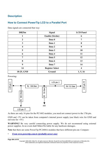
Description General Information Sum
- Page 17 and 18:
Broadcom Tigon3 Chipset type: Broad
- Page 19 and 20:
Chipset type: Marvell Yukon 88E80xx
- Page 21 and 22:
Compatibility: • RealTek RTL8129
- Page 23 and 24:
Description Atheros Chipset type: A
- Page 25 and 26:
Description This is driver for lega
- Page 27 and 28:
xDSL Packages required: synchronous
- Page 29 and 30:
License Management Document revisio
- Page 31 and 32:
Important: the abovementioned limit
- Page 33 and 34:
• ERROR: You are not allowed to u
- Page 35 and 36:
• NTP - Network Time Protocol ser
- Page 37 and 38:
package is installed) • MAC Telne
- Page 39 and 40:
Related Documents • Software Pack
- Page 41 and 42:
from this type of media; if El Tori
- Page 43 and 44:
etype new password: ************ [a
- Page 45 and 46:
| from any level [admin@MikroTik] i
- Page 47 and 48:
0 D RealTek 8139 1 D Intel EtherExp
- Page 49 and 50:
when the addresses were added in th
- Page 51 and 52:
y the ISP, you should use the sourc
- Page 53 and 54:
Installing RouterOS with CD-Install
- Page 55 and 56:
Installing RouterOS with Floppies D
- Page 57 and 58:
• IP address/mask - address with
- Page 59 and 60:
Configuration Management Document r
- Page 61 and 62:
Description The export command prin
- Page 63 and 64:
FTP (File Transfer Protocol) Server
- Page 65 and 66:
MAC Level Access (Telnet and Winbox
- Page 67 and 68:
Flags: X - disabled # INTERFACE 0 a
- Page 69 and 70:
Description The Serial Console (man
- Page 71 and 72:
Notes [Ctrl]+[Q] and [Ctrl]+[X] hav
- Page 73 and 74:
License required: level1 Home menu
- Page 75 and 76:
Uninstalling Command name: /system
- Page 77 and 78:
10 ppp 2.9.11 11 dhcp 2.9.11 12 hot
- Page 79 and 80:
To add a router with IP address 192
- Page 81 and 82:
thinrouter-pcipc forces PCI-to-Card
- Page 83 and 84:
Description In this submenu you can
- Page 85 and 86:
SSH (Secure Shell) Server and Clien
- Page 87 and 88:
Example [admin@MikroTik] > /system
- Page 89 and 90:
MikroTik RouterOS implements indust
- Page 91 and 92:
Common Console Functions Descriptio
- Page 93 and 94:
[admin@MikroTik] interface> set 0 m
- Page 95 and 96:
Description There are some commands
- Page 97 and 98:
owner of safe mode is notified abou
- Page 99 and 100:
where: • discovers and shows MNDP
- Page 101 and 102:
IP Addresses and ARP Document revis
- Page 103 and 104:
ether1 or ether2. Example [admin@Mi
- Page 105 and 106:
0 10.0.0.217/24 10.0.0.0 10.0.0.255
- Page 107 and 108:
OSPF Document revision 1.4 (Wed Dec
- Page 109 and 110:
• if-installed-as-type-1 - send t
- Page 111 and 112:
• none - do not use authenticatio
- Page 113 and 114:
[admin@MikroTik] routing ospf> inte
- Page 115 and 116:
OSPF backup without using a tunnel
- Page 117 and 118:
# NETWORK AREA 0 10.3.0.0/24 local_
- Page 119 and 120:
[admin@OSPF_peer_2] > ip route prin
- Page 121 and 122:
Packages required: routing License
- Page 123 and 124:
eceive (v1 | v1-2 | v2; default: v2
- Page 125 and 126:
Example To view the list of the rou
- Page 127 and 128:
[admin@MikroTik] routing rip> • C
- Page 129 and 130:
• dynamic routes - automatically
- Page 131 and 132:
Static Equal Cost Multi-Path routin
- Page 133 and 134:
General Interface Settings Document
- Page 135 and 136:
ARLAN 655 Wireless Client Card Docu
- Page 137 and 138:
Example [admin@MikroTik] > interfac
- Page 139 and 140:
Interface Bonding Document revision
- Page 141 and 142:
determenation relies on the device
- Page 143 and 144:
• for Office1through ISP2 [admin@
- Page 145 and 146:
Bridge Document revision 2.1 (Fri M
- Page 147 and 148:
• Filter Description Ethernet-lik
- Page 149 and 150:
To group ether1 and ether2 in the a
- Page 151 and 152:
idge1 00:C0:DF:07:5E:E6 ether1 4m46
- Page 153 and 154:
• ddp - datagram delivery protoco
- Page 155 and 156:
Home menu level: /interface bridge
- Page 157 and 158:
action=dst-nat is selected Troubles
- Page 159 and 160:
• Device Driver List • IP Addre
- Page 161 and 162:
tx-antenna (both | default | left |
- Page 163 and 164:
The access point is connected to th
- Page 165 and 166:
• One of the units (slave) should
- Page 167 and 168:
Cyclades PC300 PCI Adapters Documen
- Page 169 and 170:
chdlc-keepalive (time; default: 10s
- Page 171 and 172:
[admin@MikroTik] ip route> add gate
- Page 173 and 174:
Additional Documents • http://www
- Page 175 and 176:
ut it does not affect the NIC's per
- Page 177 and 178:
Additional Documents • http://www
- Page 179 and 180:
The interface should be enabled acc
- Page 181 and 182:
1 1.1.1.2/32 1.1.1.1 1.1.1.1 farsyn
- Page 183 and 184:
Finally we need to add IP addresses
- Page 185 and 186:
• Moxa C502 Dual Port Synchronous
- Page 187 and 188:
0 1.1.1.1/24 1.1.1.0 1.1.1.255 pvc1
- Page 189 and 190:
Troubleshooting Description • I c
- Page 191 and 192:
[admin@MikroTik] interface ppp-clie
- Page 193 and 194:
Hardware usage: Not significant Rel
- Page 195 and 196:
mtu (integer; default: 1500) - Maxi
- Page 197 and 198:
session-timeout=0s idle-timeout=0s
- Page 199 and 200:
• And finally, you have to add sc
- Page 201 and 202:
Description With the introduction o
- Page 203 and 204:
M3P Document revision 0.3.0 (Wed Ma
- Page 205 and 206:
unpacking (none | simple | compress
- Page 207 and 208:
• Log Management Description You
- Page 209 and 210:
[admin@MikroTik] interface moxa-c10
- Page 211 and 212:
[admin@MikroTik] ip route> print Fl
- Page 213 and 214:
Flags: X - disabled, I - invalid, D
- Page 215 and 216:
• Log Management Description You
- Page 217 and 218:
The driver for MOXA C502 card shoul
- Page 219 and 220:
The driver for MOXA C502 card shoul
- Page 221 and 222:
PPP and Asynchronous Interfaces Doc
- Page 223 and 224:
Example [admin@MikroTik] > /port pr
- Page 225 and 226:
Example You can add a PPP client us
- Page 227 and 228:
RadioLAN 5.8GHz Wireless Interface
- Page 229 and 230:
default-destination (ap | as-specif
- Page 231 and 232:
1. Setting the Service Set Identifi
- Page 233 and 234:
Property Description Notes WDS Inte
- Page 235 and 236:
Service Set Identifier test, do the
- Page 237 and 238:
acceptance timeout) in microseconds
- Page 239 and 240:
• manual-tx-power - channels in c
- Page 241 and 242:
Notes It is strongly suggested to l
- Page 243 and 244:
• none - do nothing special, do n
- Page 245 and 246:
WDS cannot be used on Nstreme-dual
- Page 247 and 248:
access point routeros-version (read
- Page 249 and 250:
client-tx-limit (integer; default:
- Page 251 and 252:
nstreme-support (read-only: yes | n
- Page 253 and 254:
Property Description arp (disabled
- Page 255 and 256:
Align Home menu level: /interface w
- Page 257 and 258:
2412MHz 3.8% 2417MHz 9.8% 2422MHz 2
- Page 259 and 260:
Property Description group-key-upda
- Page 261 and 262:
Prism card doesn't report that the
- Page 263 and 264:
2 2412 -45dBm@1Mbps 00:02:6F:05:68:
- Page 265 and 266:
ack-timeout=dynamic tx-power=defaul
- Page 267 and 268:
This example will show you how to c
- Page 269 and 270:
adio-name: "000C42050022" signal-st
- Page 271 and 272:
Flags: X - disabled, R - running 0
- Page 273 and 274:
[admin@WEP_StationX] interface wire
- Page 275 and 276:
Xpeed SDSL Interface Document revis
- Page 277 and 278:
[admin@r1] interface> print Flags:
- Page 279 and 280:
• I tried to connect two routers
- Page 281 and 282:
2. On router with IP address 10.1.0
- Page 283 and 284:
network. Example Our goal is to cre
- Page 285 and 286:
IP Security Document revision 3.4 (
- Page 287 and 288:
Internet Key Exchange The Internet
- Page 289 and 290:
level (acquire | require | use; def
- Page 291 and 292:
hash-algorithm (multiple choice: md
- Page 293 and 294:
current-bytes (read-only: integer)
- Page 295 and 296:
General Information MikroTik Router
- Page 297 and 298:
! Create IPsec transform set - tran
- Page 299 and 300:
[admin@MikroTik] > /ip ipsec policy
- Page 301 and 302:
1. Add an IPIP interface (by defaul
- Page 303 and 304:
[admin@MikroTik] interface ipip> pr
- Page 305 and 306:
• accessing an Intranet/LAN of a
- Page 307 and 308:
[admin@MikroTik] interface l2tp-cli
- Page 309 and 310:
[admin@MikroTik] interface l2tp-ser
- Page 311 and 312:
To route the local Intranets over t
- Page 313 and 314:
On the L2TP server a user must be s
- Page 315 and 316:
PPPoE Document revision 1.5 (Fri No
- Page 317 and 318:
License required: level1 (limited t
- Page 319 and 320:
Example To monitor the pppoe-out1 c
- Page 321 and 322:
To disconnect the user ex: [admin@M
- Page 323 and 324:
disconnect, they are still shown an
- Page 325 and 326:
• For mobile or remote clients to
- Page 327 and 328:
Example To set up PPTP client named
- Page 329 and 330:
connection mtu (integer) - (cannot
- Page 331 and 332:
ound-trip min/avg/max = 3/3.0/3 ms
- Page 333 and 334:
VLAN Document revision 1.2 (Mon Sep
- Page 335 and 336:
• http://www.cisco.com/warp/publi
- Page 337 and 338:
Graphing Document revision 1.0 (09-
- Page 339 and 340:
allow-address (IP address | netmask
- Page 341 and 342:
HotSpot User AAA Document revision
- Page 343 and 344:
name (name) - profile reference nam
- Page 345 and 346:
Example To add user ex with passwor
- Page 347 and 348:
IP accounting Document revision 2.1
- Page 349 and 350:
enabled: yes account-local-traffic:
- Page 351 and 352:
PPP User AAA Document revision 2.4
- Page 353 and 354:
was no activity present. There is n
- Page 355 and 356:
is the caller's number (that may or
- Page 357 and 358:
RADIUS client Document revision 0.4
- Page 359 and 360:
• ppp - Point-to-Point clients au
- Page 361 and 362:
address of the client) • User-Nam
- Page 363 and 364:
• Advertise-Interval - Time inter
- Page 365 and 366:
Framed-IP-Address 8 RFC2865 Framed-
- Page 367 and 368:
Router User AAA Document revision 2
- Page 369 and 370:
• password - policy that grants r
- Page 371 and 372:
when (read-only: date) - log in dat
- Page 373 and 374:
information included • version 9
- Page 375 and 376:
Bandwidth Control Document revision
- Page 377 and 378:
disciplines are set under /queue in
- Page 379 and 380:
picture, Leaf1 will be served only
- Page 381 and 382:
PFIFO and BFIFO These queuing disci
- Page 383 and 384:
Interface Default Queues Home menu
- Page 385 and 386:
Home menu level: /queue tree Descri
- Page 387 and 388:
upload to the Server and Workstatio
- Page 389 and 390:
Filter Document revision 2.7 (Fri N
- Page 391 and 392:
• packet arrival time • and muc
- Page 393 and 394:
connection-type (ftp | gre | h323 |
- Page 395 and 396:
ipsec-esp | iso-tp4 | ospf | pup |
- Page 397 and 398:
add chain=forward src-address=0.0.0
- Page 399 and 400:
The address list records could be u
- Page 401 and 402:
Mangle Home menu level: /ip firewal
- Page 403 and 404:
hotspot (multiple choice: from-clie
- Page 405 and 406:
coming from the same host to be tre
- Page 407 and 408:
Change MSS It is a well known fact
- Page 409 and 410:
NAT Description Network Address Tra
- Page 411 and 412:
chain (dstnat | srcnat | name) - sp
- Page 413 and 414:
out-interface (name) - interface th
- Page 415 and 416:
Example of Destination NAT If you w
- Page 417 and 418:
Packet Flow Description MikroTik Ro
- Page 419 and 420:
Property Description connection-mar
- Page 421 and 422:
Description ICMP TYPE:CODE values I
- Page 423 and 424:
DHCP Client and Server Document rev
- Page 425 and 426:
Flags: X - disabled, I - invalid 0
- Page 427 and 428:
DHCP Server Setup Home menu level:
- Page 429 and 430:
DHCP lease in case it is directly r
- Page 431 and 432:
6. in other case, the lease becomes
- Page 433 and 434:
Description To find any rogue DHCP
- Page 435 and 436:
• 0.0.0.0 - the IP address will b
- Page 437 and 438:
IP addresses of DHCP-Relay: [admin@
- Page 439 and 440:
DNS Client and Cache Document revis
- Page 441 and 442:
secondary-dns: 0.0.0.0 allow-remote
- Page 443 and 444:
HotSpot Gateway Document revision 4
- Page 445 and 446:
for that interface: /ip hotspot add
- Page 447 and 448:
You may wish not to require authori
- Page 449 and 450:
While client is blocked, FTP and ot
- Page 451 and 452:
set up in the server profile, and a
- Page 453 and 454:
split-user-domain (yes | no; defaul
- Page 455 and 456: • deny - the authorization is req
- Page 457 and 458: • bypassed - perform the translat
- Page 459 and 460: NAT rules From /ip firewall nat pri
- Page 461 and 462: finished session • error.html - e
- Page 463 and 464: • link-login - link to login page
- Page 465 and 466: Notes If you want to use HTTP-CHAP
- Page 467 and 468: • Hotspot will ask RADIUS server
- Page 469 and 470: that they will have login-free acce
- Page 471 and 472: [admin@MikroTik] ip proxy> print en
- Page 473 and 474: path (wildcard) - name of the reque
- Page 475 and 476: esponse may be used to update previ
- Page 477 and 478: Description IP pools simply group I
- Page 479 and 480: SOCKS Proxy Server Document revisio
- Page 481 and 482: Access List Home menu level: /ip so
- Page 483 and 484: client. In this case IP address wou
- Page 485 and 486: IP address on it, and as many inter
- Page 487 and 488: Web Proxy Document revision 1.1 (We
- Page 489 and 490: Note that it may be useful to have
- Page 491 and 492: Description Access list is implemen
- Page 493 and 494: src-address (IP address | netmask)
- Page 495 and 496: This method retrieves whatever info
- Page 497 and 498: Certificate Management Document rev
- Page 499 and 500: decrypt - decrypt and cache public
- Page 501 and 502: DDNS Update Tool Document revision
- Page 503 and 504: GPS Synchronization Document revisi
- Page 505: [admin@MikroTik] system gps> print
- Page 509 and 510: contrast: 0 [admin@MikroTik] system
- Page 511 and 512: MNDP Document revision 1.4 (Fri Mar
- Page 513 and 514: Description This submenu allows you
- Page 515 and 516: MikroTik RouterOS provides both - N
- Page 517 and 518: Home menu level: /system clock Note
- Page 519 and 520: • Health monitoring (RouterBOARD
- Page 521 and 522: • optimal - the BIOS tries to det
- Page 523 and 524: led3 (yes | no; default: no) - whet
- Page 525 and 526: Support Output File Document revisi
- Page 527 and 528: Command Description Notes Example S
- Page 529 and 530: 0xCF8-0xCFF [PCI conf1] 0x4000-0x40
- Page 531 and 532: Only users, which are members of gr
- Page 533 and 534: Home menu level: Command name: /sys
- Page 535 and 536: Bandwidth Test Document revision 1.
- Page 537 and 538: [admin@MikroTik] tool bandwidth-ser
- Page 539 and 540: ICMP Bandwidth Test Document revisi
- Page 541 and 542: Packet Sniffer Document revision 1.
- Page 543 and 544: filter-address1 and filter-address2
- Page 545 and 546: • ospf - Open Shortest Path First
- Page 547 and 548: Packet Sniffer Host Home menu level
- Page 549 and 550: Ping Document revision 1 (Mon Jul 1
- Page 551 and 552: and press the [Tab] key: [admin@Mik
- Page 553 and 554: interface (name) - the name of the
- Page 555 and 556: Traceroute Document revision 1.8 (F
- Page 557 and 558:
Network Monitor Document revision 1
- Page 559 and 560:
done There are two scripts. The scr
- Page 561 and 562:
eboot and on most item configuratio
- Page 563 and 564:
Scripting Host Document revision 2.
- Page 565 and 566:
Console commands are made of the fo
- Page 567 and 568:
Variables Description RouterOS scri
- Page 569 and 570:
= - greater or equal. Binary operat
- Page 571 and 572:
[admin@MikroTik] interface> :put (1
- Page 573 and 574:
epeatedly (yes | no) - condition, w
- Page 575 and 576:
• omitted - altar LED state forev
- Page 577 and 578:
3 4 5 6 7 8 9 [admin@MikroTik] > Sp
- Page 579 and 580:
policy (multiple choice: ftp | loca
- Page 581 and 582:
Command Description edit (name) - o
- Page 583 and 584:
interval (time; default: 0s) - inte
- Page 585 and 586:
Traffic Monitor Document revision 1
- Page 587 and 588:
IP Telephony Document revision 2.2
- Page 589 and 590:
Description IP telephony, known as
- Page 591 and 592:
If autodial does not exactly match
- Page 593 and 594:
name (name) - name given by the use
- Page 595 and 596:
ing-cadence (text) - a 16-symbol ri
- Page 597 and 598:
number of packets received by this
- Page 599 and 600:
There is a possibility to enter som
- Page 601 and 602:
ZZ • If nr=444, it matches the re
- Page 603 and 604:
To generate a tone, frequency and c
- Page 605 and 606:
• 10 - Call failed as could not f
- Page 607 and 608:
0 11 phonejack1 1 _ voip1 [admin@Mi
- Page 609 and 610:
Setting up the MikroTik IP Telephon
- Page 611 and 612:
# DST-PATTERN VOICE-PORT PREFIX 0 3
- Page 613 and 614:
• G.729a codec MUST be disabled (
- Page 615 and 616:
We want to be able to use make call
- Page 617 and 618:
no-ping-delay (time; default: 5m) -
- Page 619 and 620:
Packages required: ups License requ
- Page 621 and 622:
Notes The test begins only if the b
- Page 623 and 624:
VRRP Document revision 1.4 (Fri Mar
- Page 625 and 626:
advertisement packets • none - no
- Page 627 and 628:
This example shows how to configure