

Where am I? Sensors and Methods for Mobile Robot Positioning
Where am I? Sensors and Methods for Mobile Robot Positioning
Where am I? Sensors and Methods for Mobile Robot Positioning

You also want an ePaper? Increase the reach of your titles
YUMPU automatically turns print PDFs into web optimized ePapers that Google loves.
200 Part II Systems <strong>and</strong> <strong>Methods</strong> <strong>for</strong> <strong>Mobile</strong> <strong>Robot</strong> <strong>Positioning</strong><br />
model against the observed segment, to allow detection of similarity in orientation, collinearity, <strong>and</strong><br />
overlap. Each of these tests is made by comparing one of the par<strong>am</strong>eters in the segment representation:<br />
a. Orientation The square of the difference in orientation of the two c<strong>and</strong>idates must be smaller<br />
than the sum of the variances.<br />
b. Alignment The square of the difference of the distance from the origin to the two c<strong>and</strong>idates<br />
must be smaller than the sum of the corresponding variance.<br />
c. Overlap The difference of the distance between centerpoints to the sum of the half lengths must<br />
be smaller than a threshold.<br />
The longest segment in the composite local model which passes all three tests is selected as the<br />
matching segment. The segment is then used to correct the estimated position of the robot <strong>and</strong> to<br />
update the model. An explicit model of uncertainty using covariance <strong>and</strong> Kalman filtering provides<br />
a tool <strong>for</strong> integrating noisy <strong>and</strong> imprecise sensor observations into the model of the geometric limits<br />
<strong>for</strong> the free space of a vehicle. Such a model provides a means <strong>for</strong> a vehicle to maintain an estimate<br />
of its position as it travels, even in the case where the environment is unknown.<br />
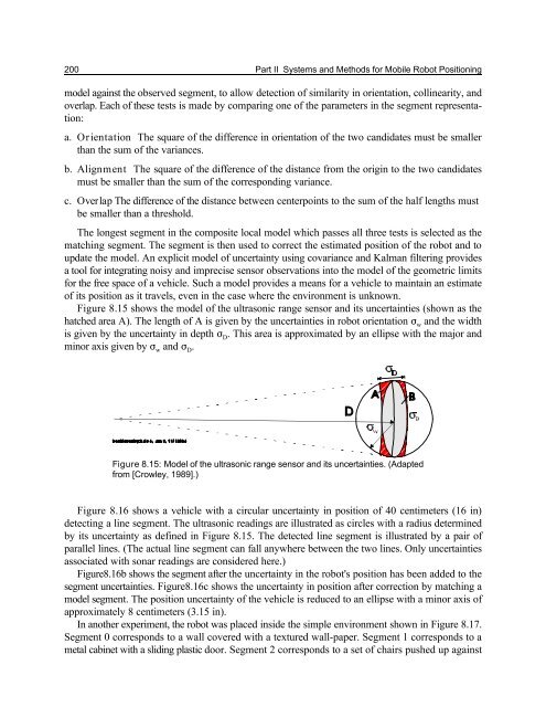
Figure 8.15 shows the model of the ultrasonic range sensor <strong>and</strong> its uncertainties (shown as the<br />
hatched area A). The length of A is given by the uncertainties in robot orientation F <strong>and</strong> the width<br />
w<br />
is given by the uncertainty in depth F . This area is approximated by an ellipse with the major <strong>and</strong><br />
D<br />
minor axis given by F w <strong>and</strong> F D.<br />
Figure 8.15: Model of the ultrasonic range sensor <strong>and</strong> its uncertainties. (Adapted<br />
from [Crowley, 1989].)<br />
Figure 8.16 shows a vehicle with a circular uncertainty in position of 40 centimeters (16 in)<br />
detecting a line segment. The ultrasonic readings are illustrated as circles with a radius determined<br />
by its uncertainty as defined in Figure 8.15. The detected line segment is illustrated by a pair of<br />
parallel lines. (The actual line segment can fall anywhere between the two lines. Only uncertainties<br />
associated with sonar readings are considered here.)<br />
Figure8.16b shows the segment after the uncertainty in the robot's position has been added to the<br />
segment uncertainties. Figure8.16c shows the uncertainty in position after correction by matching a<br />
model segment. The position uncertainty of the vehicle is reduced to an ellipse with a minor axis of<br />
approximately 8 centimeters (3.15 in).<br />
In another experiment, the robot was placed inside the simple environment shown in Figure 8.17.<br />
Segment 0 corresponds to a wall covered with a textured wall-paper. Segment 1 corresponds to a<br />
metal cabinet with a sliding plastic door. Segment 2 corresponds to a set of chairs pushed up against


