

Where am I? Sensors and Methods for Mobile Robot Positioning
Where am I? Sensors and Methods for Mobile Robot Positioning
Where am I? Sensors and Methods for Mobile Robot Positioning

You also want an ePaper? Increase the reach of your titles
YUMPU automatically turns print PDFs into web optimized ePapers that Google loves.
Chapter 2: Heading <strong>Sensors</strong> 47<br />
Dinsmore Starguide Magnetic Compass<br />
An extremely low-cost configuration of the mechanical magnetic compass suitable <strong>for</strong> robotic<br />
applications is seen in a product recently announced by the Dinsmore Instrument Company, Flint,<br />
MI. The heart of the Starguide compass is the Dinsmore model 1490 digital sensor [Dinsmore<br />
Instrument Company, 1991], which consists of a miniaturized permanent-magnet rotor mounted in<br />
low-friction jeweled bearings. The sensor is internally d<strong>am</strong>ped such that if momentarily displaced<br />
90 degrees, it will return to the indicated direction in 2.5 seconds, with no overshoot.<br />
Four Hall-effect switches corresponding to the cardinal headings (N, E, W, S) are arranged<br />
around the periphery of the rotor <strong>and</strong> activated by the south pole of the magnet as the rotor aligns<br />
itself with the earth’s magnetic field. Intermediate headings (NE, NW, SE, SW) are indicated through<br />
simultaneous activation of the adjacent cardinal-heading switches. The Dinsmore Starguide is not<br />
a true Hall-effect compass (see Sec. 2.4.3), in that the Hall-effect devices are not directly sensing<br />
the geomagnetic field of the earth, but rather the angular position of a mechanical rotor.<br />
The model 1490 digital sensor measures 12.5 millimeters (0.5 in) in di<strong>am</strong>eter by 16 millimeters<br />
(0.63 in) high, <strong>and</strong> is available separately from Dinsmore <strong>for</strong> around $12. Current consumption is<br />
30 mA, <strong>and</strong> the open-collector NPN outputs can sink 25 mA per channel. Grenoble [1990] presents<br />
a simple circuit <strong>for</strong> interfacing the device to eight indicator LEDs. An alternative analog sensor<br />
(model 1525) with a ratiometric sine-cosine output is also available <strong>for</strong> around $35. Both sensors<br />
may be subjected to unlimited magnetic flux without d<strong>am</strong>age.<br />
2.4.2 Fluxgate Compasses<br />
There currently is no practical alternative to the popular fluxgate compass <strong>for</strong> portability <strong>and</strong> long<br />
missions [Fenn et al., 1992]. The term fluxgate is actually a trade n<strong>am</strong>e of Pioneer Bendix <strong>for</strong> the<br />
saturable-core magnetometer, derived from the gating action imposed by an AC-driven excitation<br />
coil that induces a time varying permeability in the sensor core. Be<strong>for</strong>e discussing the principle of<br />
operation, it is probably best to review briefly the subject of magnetic conductance, or permeability.<br />
The permeability µ of a given material is a measure of how well it serves as a path <strong>for</strong> magnetic<br />
lines of <strong>for</strong>ce, relative to air, which has an assigned permeability of one. Some ex<strong>am</strong>ples of highpermeability<br />
materials are listed in Table 2.3.<br />
Permeability is the magnetic circuit analogy<br />
to electrical conductivity, <strong>and</strong> relates<br />
magnetic flux density to the magnetizing<br />
<strong>for</strong>ce as follows:<br />
B = µ H (2.10)<br />
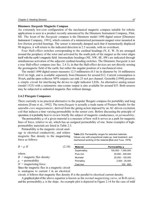
Table 2.3: Permeability ranges <strong>for</strong> selected materials.<br />
Values vary with proportional make-up, heat treatment, <strong>and</strong><br />
mechanical working of the material [Bolz <strong>and</strong> Tuve, 1979].<br />
Material Permeability µ<br />
Supermalloy 100,000 - 1,000,000<br />
Pure iron 25,000 - 300,000<br />
Mumetal 20,000 - 100,000<br />
Permalloy 2,500 - 25,000<br />
Cast iron 100 - 600<br />
where<br />
B = magnetic flux density<br />
µ = permeability<br />
H = magnetizing <strong>for</strong>ce.<br />
Since the magnetic flux in a magnetic circuit<br />
is analogous to current I in an electrical<br />
circuit, it follows that magnetic flux density B is the parallel to electrical current density.<br />
A graphical plot of the above equation is known as the normal magnetizing curve, or B-H curve,<br />
<strong>and</strong> the permeability µ is the slope. An ex<strong>am</strong>ple plot is depicted in Figure 2.14 <strong>for</strong> the case of mild


