H.264 4/8/16-Channel DVR User Manual - Security Cameras Direct
H.264 4/8/16-Channel DVR User Manual - Security Cameras Direct
H.264 4/8/16-Channel DVR User Manual - Security Cameras Direct

You also want an ePaper? Increase the reach of your titles
YUMPU automatically turns print PDFs into web optimized ePapers that Google loves.
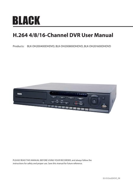
<strong>H.264</strong> 4/8/<strong>16</strong>-<strong>Channel</strong> <strong>DVR</strong> <strong>User</strong> <strong>Manual</strong><br />
Products:<br />
BLK-DH200400DHDVD, BLK-DH200800DHDVD, BLK-DH20<strong>16</strong>00DHDVD<br />
PLEASE READ THIS MANUAL BEFORE USING YOUR RECORDER, and always follow the<br />
instructions for safety and proper use. Save this manual for future reference.<br />
BLK-DH20xx00DHDVD_RM
CAUTION<br />
Operate this system only in environments where the temperature and humidity is within the recommended range.<br />
Operation in temperatures or at humidity levels outside the recommended range may cause electric shock and shorten the<br />
life of the product. Refer to the specifications for each system component for more information.<br />
LEGAL NOTICE<br />
Observint Technologies (Observint) products are designed to meet safety and performance standards with the use of<br />
specific Observint authorized accessories. Observint disclaims liability associated with the use of non-Observint<br />
authorized accessories.<br />
The recording, transmission, or broadcast of any person’s voice without their consent or a court order is strictly<br />
prohibited by law.<br />
Observint makes no representations concerning the legality of certain product applications such as the making,<br />
transmission, or recording of video and/or audio signals of others without their knowledge and/or consent. We<br />
encourage you to check and comply with all applicable local, state, and federal laws and regulations before<br />
engaging in any form of surveillance or any transmission of radio frequencies.<br />
Microsoft, Windows, Windows Media, and Internet Explorer are either registered trademarks or trademarks of Microsoft<br />
Corporation in the United States and/or other countries. Android is a trademark of Google Inc. Use of this trademark<br />
is subject to Google Permissions. Apple, iPhone, iPod touch, and iPad are registered trademarks of Apple Inc. Intel and<br />
Pentium are trademarks of Intel Corporation in the U.S. and/or other countries.<br />
Other trademarks and trade names may be used in this document to refer to either the entities claiming the marks<br />
and names or their products. Observint disclaims any proprietary interest in trademarks and trade names other than<br />
its own.<br />
No part of this document may be reproduced or distributed in any form or by any means without the express written<br />
permission of Observint, Inc.<br />
© 2012 by Observint Technologies, Inc. All Rights Reserved.<br />
11000 N. Mopac Expressway, Building 300, Austin, TX 78759<br />
For Sales and Support, contact your distributor.<br />
ii
Table of Contents<br />
SECTION 1 Introduction . . . . . . . . . . . . . . . . . . . . . . . . . . . . . . . . . . . . . . . . . . . . . . . . . . . . . . . . . . . . . . . . . . . . . . . 1<br />
SECTION 2 Hardware Overview and Setup . . . . . . . . . . . . . . . . . . . . . . . . . . . . . . . . . . . . . . . . . . . . . . . . . . . . . . . . 2<br />
2.1 Front panel controls and indicators . . . . . . . . . . . . . . . . . . . . . . . . . . . . . . . . . . . . . . . . . . . . . . . . . . . . .2<br />
2.2 Back panel connectors . . . . . . . . . . . . . . . . . . . . . . . . . . . . . . . . . . . . . . . . . . . . . . . . . . . . . . . . . . . . . . . .4<br />
2.2.1 BLK-DH200400DHDVD . . . . . . . . . . . . . . . . . . . . . . . . . . . . . . . . . . . . . . . . . . . . . . . . . . . . . . . . . . .4<br />
2.2.2 BLK-DH200800DHDVD . . . . . . . . . . . . . . . . . . . . . . . . . . . . . . . . . . . . . . . . . . . . . . . . . . . . . . . . . . .5<br />
2.2.3 BLK-DH20<strong>16</strong>00DHDVD . . . . . . . . . . . . . . . . . . . . . . . . . . . . . . . . . . . . . . . . . . . . . . . . . . . . . . . . . . .6<br />
2.2.4 RS485, sensor and alarm termination block . . . . . . . . . . . . . . . . . . . . . . . . . . . . . . . . . . . . . . . . . .7<br />
2.3 Remote Control . . . . . . . . . . . . . . . . . . . . . . . . . . . . . . . . . . . . . . . . . . . . . . . . . . . . . . . . . . . . . . . . . . . . . .8<br />
2.4 DVD-R/W Optical drive installation . . . . . . . . . . . . . . . . . . . . . . . . . . . . . . . . . . . . . . . . . . . . . . . . . . . . .9<br />
2.5 HDD installation . . . . . . . . . . . . . . . . . . . . . . . . . . . . . . . . . . . . . . . . . . . . . . . . . . . . . . . . . . . . . . . . . . . .12<br />
2.5.1 Installing a 2nd internal HDD . . . . . . . . . . . . . . . . . . . . . . . . . . . . . . . . . . . . . . . . . . . . . . . . . . . . .<strong>16</strong><br />
SECTION 3 System Setup . . . . . . . . . . . . . . . . . . . . . . . . . . . . . . . . . . . . . . . . . . . . . . . . . . . . . . . . . . . . . . . . . . . . . . 17<br />
3.1 Starting the system for the first time . . . . . . . . . . . . . . . . . . . . . . . . . . . . . . . . . . . . . . . . . . . . . . . . . . .17<br />
3.1.1 Entering the SETUP menu . . . . . . . . . . . . . . . . . . . . . . . . . . . . . . . . . . . . . . . . . . . . . . . . . . . . . . . .18<br />
3.2 DISPLAY menu . . . . . . . . . . . . . . . . . . . . . . . . . . . . . . . . . . . . . . . . . . . . . . . . . . . . . . . . . . . . . . . . . . . . . .20<br />
3.3 RECORD menu . . . . . . . . . . . . . . . . . . . . . . . . . . . . . . . . . . . . . . . . . . . . . . . . . . . . . . . . . . . . . . . . . . . . . .21<br />
3.3.1 Recording Schedules . . . . . . . . . . . . . . . . . . . . . . . . . . . . . . . . . . . . . . . . . . . . . . . . . . . . . . . . . . . .22<br />
3.4 DEVICE menu . . . . . . . . . . . . . . . . . . . . . . . . . . . . . . . . . . . . . . . . . . . . . . . . . . . . . . . . . . . . . . . . . . . . . . .24<br />
3.5 STORAGE menu . . . . . . . . . . . . . . . . . . . . . . . . . . . . . . . . . . . . . . . . . . . . . . . . . . . . . . . . . . . . . . . . . . . . .27<br />
3.6 SYSTEM menu . . . . . . . . . . . . . . . . . . . . . . . . . . . . . . . . . . . . . . . . . . . . . . . . . . . . . . . . . . . . . . . . . . . . . .30<br />
3.7 SECURITY menu. . . . . . . . . . . . . . . . . . . . . . . . . . . . . . . . . . . . . . . . . . . . . . . . . . . . . . . . . . . . . . . . . . . . .32<br />
3.8 NETWORK menu . . . . . . . . . . . . . . . . . . . . . . . . . . . . . . . . . . . . . . . . . . . . . . . . . . . . . . . . . . . . . . . . . . . .34<br />
3.8.1 Network ports . . . . . . . . . . . . . . . . . . . . . . . . . . . . . . . . . . . . . . . . . . . . . . . . . . . . . . . . . . . . . . . . .36<br />
3.9 CONFIG menu . . . . . . . . . . . . . . . . . . . . . . . . . . . . . . . . . . . . . . . . . . . . . . . . . . . . . . . . . . . . . . . . . . . . . .37<br />
SECTION 4 Live, Search, and Playback . . . . . . . . . . . . . . . . . . . . . . . . . . . . . . . . . . . . . . . . . . . . . . . . . . . . . . . . . . . 39<br />
4.1 SEARCH menu . . . . . . . . . . . . . . . . . . . . . . . . . . . . . . . . . . . . . . . . . . . . . . . . . . . . . . . . . . . . . . . . . . . . . .41<br />
4.1.1 TIME-LINE search . . . . . . . . . . . . . . . . . . . . . . . . . . . . . . . . . . . . . . . . . . . . . . . . . . . . . . . . . . . . . . .42<br />
4.1.2 EVENT search . . . . . . . . . . . . . . . . . . . . . . . . . . . . . . . . . . . . . . . . . . . . . . . . . . . . . . . . . . . . . . . . . .43<br />
4.1.3 GO TO FIRST TIME search . . . . . . . . . . . . . . . . . . . . . . . . . . . . . . . . . . . . . . . . . . . . . . . . . . . . . . . . .43<br />
4.1.4 GO TO LAST TIME search. . . . . . . . . . . . . . . . . . . . . . . . . . . . . . . . . . . . . . . . . . . . . . . . . . . . . . . . . .43<br />
4.1.5 GO TO SPECIFIC TIME search . . . . . . . . . . . . . . . . . . . . . . . . . . . . . . . . . . . . . . . . . . . . . . . . . . . . . .43<br />
4.2 ARCHIVE search . . . . . . . . . . . . . . . . . . . . . . . . . . . . . . . . . . . . . . . . . . . . . . . . . . . . . . . . . . . . . . . . . . . . .44<br />
<strong>H.264</strong> <strong>DVR</strong> <strong>User</strong> <strong>Manual</strong><br />
iii
TABLE OF CONTENTS<br />
4.3 PLAY mode . . . . . . . . . . . . . . . . . . . . . . . . . . . . . . . . . . . . . . . . . . . . . . . . . . . . . . . . . . . . . . . . . . . . . . . . .45<br />
4.4 Backup video clip . . . . . . . . . . . . . . . . . . . . . . . . . . . . . . . . . . . . . . . . . . . . . . . . . . . . . . . . . . . . . . . . . . .46<br />
SECTION 5 PTZ Control . . . . . . . . . . . . . . . . . . . . . . . . . . . . . . . . . . . . . . . . . . . . . . . . . . . . . . . . . . . . . . . . . . . . . . . . 48<br />
SECTION 6 Backup . . . . . . . . . . . . . . . . . . . . . . . . . . . . . . . . . . . . . . . . . . . . . . . . . . . . . . . . . . . . . . . . . . . . . . . . . . . 49<br />
6.1 Still image BACKUP onto USB flash drive . . . . . . . . . . . . . . . . . . . . . . . . . . . . . . . . . . . . . . . . . . . . . . . .49<br />
6.2 Video BACKUP . . . . . . . . . . . . . . . . . . . . . . . . . . . . . . . . . . . . . . . . . . . . . . . . . . . . . . . . . . . . . . . . . . . . . .49<br />
6.3 BACKUP still images or video from the ARCHIVE list . . . . . . . . . . . . . . . . . . . . . . . . . . . . . . . . . . . . . .50<br />
6.4 Playing backed up video clips . . . . . . . . . . . . . . . . . . . . . . . . . . . . . . . . . . . . . . . . . . . . . . . . . . . . . . . . .51<br />
SECTION 7 Remote Client Software . . . . . . . . . . . . . . . . . . . . . . . . . . . . . . . . . . . . . . . . . . . . . . . . . . . . . . . . . . . . . 52<br />
7.1 PC Requirements . . . . . . . . . . . . . . . . . . . . . . . . . . . . . . . . . . . . . . . . . . . . . . . . . . . . . . . . . . . . . . . . . . . .52<br />
7.2 Installing the Remote Client . . . . . . . . . . . . . . . . . . . . . . . . . . . . . . . . . . . . . . . . . . . . . . . . . . . . . . . . . .52<br />
7.3 Remote Client initial display . . . . . . . . . . . . . . . . . . . . . . . . . . . . . . . . . . . . . . . . . . . . . . . . . . . . . . . . . .53<br />
7.4 Setup . . . . . . . . . . . . . . . . . . . . . . . . . . . . . . . . . . . . . . . . . . . . . . . . . . . . . . . . . . . . . . . . . . . . . . . . . . . . .55<br />
7.4.1 General Setup . . . . . . . . . . . . . . . . . . . . . . . . . . . . . . . . . . . . . . . . . . . . . . . . . . . . . . . . . . . . . . . . . .55<br />
7.4.2 Site Setup . . . . . . . . . . . . . . . . . . . . . . . . . . . . . . . . . . . . . . . . . . . . . . . . . . . . . . . . . . . . . . . . . . . . .56<br />
7.4.3 Event Setup . . . . . . . . . . . . . . . . . . . . . . . . . . . . . . . . . . . . . . . . . . . . . . . . . . . . . . . . . . . . . . . . . . . .57<br />
7.4.4 Event Search Setup . . . . . . . . . . . . . . . . . . . . . . . . . . . . . . . . . . . . . . . . . . . . . . . . . . . . . . . . . . . . .58<br />
7.4.5 Record Setup . . . . . . . . . . . . . . . . . . . . . . . . . . . . . . . . . . . . . . . . . . . . . . . . . . . . . . . . . . . . . . . . . .59<br />
7.4.6 Record Disk Setup . . . . . . . . . . . . . . . . . . . . . . . . . . . . . . . . . . . . . . . . . . . . . . . . . . . . . . . . . . . . . .59<br />
7.4.7 Display Setup . . . . . . . . . . . . . . . . . . . . . . . . . . . . . . . . . . . . . . . . . . . . . . . . . . . . . . . . . . . . . . . . . .60<br />
7.4.8 Language Setup . . . . . . . . . . . . . . . . . . . . . . . . . . . . . . . . . . . . . . . . . . . . . . . . . . . . . . . . . . . . . . . .60<br />
7.5 Connecting to a <strong>DVR</strong> . . . . . . . . . . . . . . . . . . . . . . . . . . . . . . . . . . . . . . . . . . . . . . . . . . . . . . . . . . . . . . . . .60<br />
7.5.1 Bidirectional Audio . . . . . . . . . . . . . . . . . . . . . . . . . . . . . . . . . . . . . . . . . . . . . . . . . . . . . . . . . . . . .61<br />
7.6 Remote Search mode and functions . . . . . . . . . . . . . . . . . . . . . . . . . . . . . . . . . . . . . . . . . . . . . . . . . . .62<br />
7.6.1 Searching for and playing video recorded by the <strong>DVR</strong> . . . . . . . . . . . . . . . . . . . . . . . . . . . . . . . .63<br />
7.6.2 Backing up video from the <strong>DVR</strong> on the Remote Client PC . . . . . . . . . . . . . . . . . . . . . . . . . . . . . .64<br />
7.6.3 Image capture . . . . . . . . . . . . . . . . . . . . . . . . . . . . . . . . . . . . . . . . . . . . . . . . . . . . . . . . . . . . . . . . .66<br />
SECTION 8 Multi Client Software . . . . . . . . . . . . . . . . . . . . . . . . . . . . . . . . . . . . . . . . . . . . . . . . . . . . . . . . . . . . . . 67<br />
8.1 PC Requirements . . . . . . . . . . . . . . . . . . . . . . . . . . . . . . . . . . . . . . . . . . . . . . . . . . . . . . . . . . . . . . . . . . . .67<br />
8.2 Installing the Multi Client . . . . . . . . . . . . . . . . . . . . . . . . . . . . . . . . . . . . . . . . . . . . . . . . . . . . . . . . . . . .67<br />
8.3 Multi Client initial display . . . . . . . . . . . . . . . . . . . . . . . . . . . . . . . . . . . . . . . . . . . . . . . . . . . . . . . . . . . .68<br />
8.3.1 Using Net Finder . . . . . . . . . . . . . . . . . . . . . . . . . . . . . . . . . . . . . . . . . . . . . . . . . . . . . . . . . . . . . . . .70<br />
8.3.2 Event List . . . . . . . . . . . . . . . . . . . . . . . . . . . . . . . . . . . . . . . . . . . . . . . . . . . . . . . . . . . . . . . . . . . . . .71<br />
8.4 Setup . . . . . . . . . . . . . . . . . . . . . . . . . . . . . . . . . . . . . . . . . . . . . . . . . . . . . . . . . . . . . . . . . . . . . . . . . . . . .72<br />
8.4.1 General Setup . . . . . . . . . . . . . . . . . . . . . . . . . . . . . . . . . . . . . . . . . . . . . . . . . . . . . . . . . . . . . . . . . .72<br />
iv
TABLE OF CONTENTS<br />
8.4.2 Event Setup . . . . . . . . . . . . . . . . . . . . . . . . . . . . . . . . . . . . . . . . . . . . . . . . . . . . . . . . . . . . . . . . . . . .72<br />
8.4.3 Event Search Setup . . . . . . . . . . . . . . . . . . . . . . . . . . . . . . . . . . . . . . . . . . . . . . . . . . . . . . . . . . . . .73<br />
8.4.4 Record Setup . . . . . . . . . . . . . . . . . . . . . . . . . . . . . . . . . . . . . . . . . . . . . . . . . . . . . . . . . . . . . . . . . .74<br />
8.4.5 Record Disk Setup . . . . . . . . . . . . . . . . . . . . . . . . . . . . . . . . . . . . . . . . . . . . . . . . . . . . . . . . . . . . . .75<br />
8.4.6 Display Setup . . . . . . . . . . . . . . . . . . . . . . . . . . . . . . . . . . . . . . . . . . . . . . . . . . . . . . . . . . . . . . . . . .75<br />
8.4.7 About Setup . . . . . . . . . . . . . . . . . . . . . . . . . . . . . . . . . . . . . . . . . . . . . . . . . . . . . . . . . . . . . . . . . . .76<br />
8.5 Connecting to a <strong>DVR</strong> . . . . . . . . . . . . . . . . . . . . . . . . . . . . . . . . . . . . . . . . . . . . . . . . . . . . . . . . . . . . . . . . .76<br />
8.5.1 Bidirectional Audio . . . . . . . . . . . . . . . . . . . . . . . . . . . . . . . . . . . . . . . . . . . . . . . . . . . . . . . . . . . . .78<br />
8.5.2 Capture . . . . . . . . . . . . . . . . . . . . . . . . . . . . . . . . . . . . . . . . . . . . . . . . . . . . . . . . . . . . . . . . . . . . . . .78<br />
8.5.3 Record . . . . . . . . . . . . . . . . . . . . . . . . . . . . . . . . . . . . . . . . . . . . . . . . . . . . . . . . . . . . . . . . . . . . . . . .79<br />
8.6 Remote playback and backup . . . . . . . . . . . . . . . . . . . . . . . . . . . . . . . . . . . . . . . . . . . . . . . . . . . . . . . . .79<br />
8.6.1 Remote playback . . . . . . . . . . . . . . . . . . . . . . . . . . . . . . . . . . . . . . . . . . . . . . . . . . . . . . . . . . . . . . .79<br />
8.6.2 Backing up video from the <strong>DVR</strong> on the Multi Client PC . . . . . . . . . . . . . . . . . . . . . . . . . . . . . . . .81<br />
8.7 Local playback . . . . . . . . . . . . . . . . . . . . . . . . . . . . . . . . . . . . . . . . . . . . . . . . . . . . . . . . . . . . . . . . . . . . . .82<br />
8.7.1 AVI backup during playback . . . . . . . . . . . . . . . . . . . . . . . . . . . . . . . . . . . . . . . . . . . . . . . . . . . . .84<br />
SECTION 9 Web Client . . . . . . . . . . . . . . . . . . . . . . . . . . . . . . . . . . . . . . . . . . . . . . . . . . . . . . . . . . . . . . . . . . . . . . . . 86<br />
9.1 Connecting to the <strong>DVR</strong> with IE . . . . . . . . . . . . . . . . . . . . . . . . . . . . . . . . . . . . . . . . . . . . . . . . . . . . . . . .86<br />
9.2 Setup . . . . . . . . . . . . . . . . . . . . . . . . . . . . . . . . . . . . . . . . . . . . . . . . . . . . . . . . . . . . . . . . . . . . . . . . . . . . .91<br />
9.2.1 Setup DISPLAY . . . . . . . . . . . . . . . . . . . . . . . . . . . . . . . . . . . . . . . . . . . . . . . . . . . . . . . . . . . . . . . . .92<br />
9.2.2 Setup RECORD. . . . . . . . . . . . . . . . . . . . . . . . . . . . . . . . . . . . . . . . . . . . . . . . . . . . . . . . . . . . . . . . . .92<br />
9.2.3 Setup DEVICE . . . . . . . . . . . . . . . . . . . . . . . . . . . . . . . . . . . . . . . . . . . . . . . . . . . . . . . . . . . . . . . . . .93<br />
9.2.4 Setup STORAGE . . . . . . . . . . . . . . . . . . . . . . . . . . . . . . . . . . . . . . . . . . . . . . . . . . . . . . . . . . . . . . . . .94<br />
9.2.5 Setup SYSTEM . . . . . . . . . . . . . . . . . . . . . . . . . . . . . . . . . . . . . . . . . . . . . . . . . . . . . . . . . . . . . . . . . .95<br />
9.2.6 Setup SECURITY . . . . . . . . . . . . . . . . . . . . . . . . . . . . . . . . . . . . . . . . . . . . . . . . . . . . . . . . . . . . . . . .95<br />
9.2.7 Setup NETWORK . . . . . . . . . . . . . . . . . . . . . . . . . . . . . . . . . . . . . . . . . . . . . . . . . . . . . . . . . . . . . . . .96<br />
9.2.8 Setup UPGRADE . . . . . . . . . . . . . . . . . . . . . . . . . . . . . . . . . . . . . . . . . . . . . . . . . . . . . . . . . . . . . . . .97<br />
9.2.9 Setup INFORMATION . . . . . . . . . . . . . . . . . . . . . . . . . . . . . . . . . . . . . . . . . . . . . . . . . . . . . . . . . . . .97<br />
9.3 <strong>DVR</strong> Search. . . . . . . . . . . . . . . . . . . . . . . . . . . . . . . . . . . . . . . . . . . . . . . . . . . . . . . . . . . . . . . . . . . . . . . . .97<br />
9.3.1 Playing recorded video . . . . . . . . . . . . . . . . . . . . . . . . . . . . . . . . . . . . . . . . . . . . . . . . . . . . . . . . . .99<br />
9.4 Backup recorded video . . . . . . . . . . . . . . . . . . . . . . . . . . . . . . . . . . . . . . . . . . . . . . . . . . . . . . . . . . . . . .100<br />
9.4.1 Capture . . . . . . . . . . . . . . . . . . . . . . . . . . . . . . . . . . . . . . . . . . . . . . . . . . . . . . . . . . . . . . . . . . . . . .100<br />
SECTION 10 Specifications . . . . . . . . . . . . . . . . . . . . . . . . . . . . . . . . . . . . . . . . . . . . . . . . . . . . . . . . . . . . . . . . . . . . 102<br />
APPENDIX A <strong>DVR</strong> Compatible Hard Disk Drives . . . . . . . . . . . . . . . . . . . . . . . . . . . . . . . . . . . . . . . . . . . . . . . . . . . . 104<br />
APPENDIX B Estimated Storage Capacity. . . . . . . . . . . . . . . . . . . . . . . . . . . . . . . . . . . . . . . . . . . . . . . . . . . . . . . . . 106<br />
APPENDIX C Device Log . . . . . . . . . . . . . . . . . . . . . . . . . . . . . . . . . . . . . . . . . . . . . . . . . . . . . . . . . . . . . . . . . . . . . . . 107<br />
APPENDIX D <strong>DVR</strong> Setup Menu Components . . . . . . . . . . . . . . . . . . . . . . . . . . . . . . . . . . . . . . . . . . . . . . . . . . . . . . 108<br />
<strong>H.264</strong> <strong>DVR</strong> <strong>User</strong> <strong>Manual</strong><br />
v
SECTION 1: INTRODUCTION<br />
SECTION 1<br />
Introduction<br />
Features<br />
• <strong>H.264</strong> Video Compression<br />
• Reliable File System<br />
• Live and Event Pop-up<br />
• VGA display interface (1280 x 1024)<br />
• 4 <strong>Channel</strong> Audio Recording<br />
• Bidirectional Audio<br />
• Individual <strong>Channel</strong> Operation<br />
• Motion Detection<br />
• Automatic Video Input and Video Loss Detection<br />
• Covert Camera Operation Provides Enhanced <strong>Security</strong><br />
• Built-In PTZ Camera Control<br />
• <strong>User</strong> friendly operator interface<br />
• Record scheduler<br />
• Software upgradable<br />
• Backup via USB flash drive, Network or DVD-R/W<br />
• Exclusive file format backup<br />
• AVI backup<br />
• Network Access via Web Client (embedded browser-based client), UMS Client (for monitoring a single <strong>DVR</strong>), Multi Client (for<br />
monitoring multiple <strong>DVR</strong>s concurrently), and smartphone apps for Apple® iPhone® and Android.<br />
Your <strong>DVR</strong> includes:<br />
• <strong>DVR</strong> with DVD-R/W drive and hard disk drive (HDD)<br />
• Software CD containing the UMS Client, Multi Client, and the <strong>DVR</strong> user manual (this document)<br />
• Remote Control<br />
• Battery 1.5V (2 x AAA)<br />
• Power Adaptor (12VDC, 5A) and cable<br />
• Mouse<br />
• Quick Start Guide document<br />
<strong>H.264</strong> <strong>DVR</strong> <strong>User</strong> <strong>Manual</strong><br />
1
SECTION 2: HARDWARE OVERVIEW AND SETUP<br />
SECTION 2<br />
Hardware Overview and Setup<br />
2.1 Front panel controls and indicators<br />
4/8/<strong>16</strong> <strong>Channel</strong> <strong>DVR</strong> Front Panel<br />
Table 1. Front Panel LED Indicators<br />
No. Name Description<br />
A CH1~<strong>16</strong> Indicates that the channel is being recorded.<br />
B HDD Indicates that the system is accessing the hard disk.<br />
C ALARM Indicates when a sensor is triggered or motion is detected.<br />
D NETWORK Indicates that a network client is connected.<br />
E BACKUP Indicates that a USB or DVD-R/W storage device is storing images or video.<br />
F POWER Indicates that the system is switched on.<br />
Table 2. Front Panel Buttons<br />
No. Name Description<br />
1<br />
<strong>Channel</strong> keys. For channel 10, press the 0 key. For channel 11, press the +10 and 1 key. For channel <strong>16</strong>, press the +10<br />
and 6 key.<br />
2 Press to rewind the video in playback mode.<br />
AUDIO<br />
3 .. <br />
Press to select audio mode such as SINGLE (highlighted channel), MIX (combine all channels), or MUTE (all channels).<br />
2
SECTION 2: HARDWARE OVERVIEW AND SETUP<br />
No. Name Description<br />
AUDIO<br />
4 .. <br />
Jump/step backward. In playback mode, the playback position moves 60 seconds backward.<br />
5 Press to fast forward the footage in playback mode.<br />
ALARM<br />
6 ..<br />
Press to enable/disable ALARM operation.<br />
ALARM<br />
7 ..<br />
Jump/Step forward. In playback mode, the playback position moves 60 seconds forward.<br />
8<br />
REC<br />
Press to start or stop manual recording.<br />
SEARCH<br />
9 / ll<br />
Press to open the SEARCH menu in live display mode.<br />
SEARCH<br />
10 / ll<br />
Press to play/pause the recording in playback mode.<br />
11<br />
SETUP<br />
Press to enter SETUP menu.<br />
12<br />
SEQ<br />
Enable/disable the automatic sequence display of channels in full screen, quad-split, and 9-split display mode.<br />
13<br />
PTZ<br />
Press to control Pan/Tilt/Zoom operations.<br />
14<br />
BACKUP<br />
Press to capture live or playback mode video in JPEG format.<br />
15 t (LEFT) Press to move left or to change the values in Setup mode. When entering a password, it inserts a 4.<br />
<strong>16</strong> p (UP) Press to move up the menu in Setup mode. When entering a password, it inserts a 1.<br />
17 u (RIGHT) Press to move right or to change the values in Setup mode. When entering a password, it inserts a 2.<br />
18 q (DOWN) Press to move down the menu in Setup mode. When entering a password, it inserts a 3.<br />
19 SEL<br />
Press to select desired menu item or to store the setup value.<br />
20<br />
ESC<br />
Press for temporary storage of the changed value or to return to the previous menu screen.<br />
21 USB Port<br />
Use with a USB flash drive to archive still images and videos, and upgrade firmware, or use to connect a USB mouse to<br />
the <strong>DVR</strong>.<br />
22<br />
<br />
To open and close the insert tray, press the button<br />
23 DVD Drive To save video, insert a CD-R/DVD-R<br />
<strong>H.264</strong> <strong>DVR</strong> <strong>User</strong> <strong>Manual</strong><br />
3
SECTION 2: HARDWARE OVERVIEW AND SETUP<br />
2.2 Back panel connectors<br />
2.2.1 BLK-DH200400DHDVD<br />
4-<strong>Channel</strong> <strong>DVR</strong> Rear Panel<br />
Table 3. BLK-DH200400DHDVD Rear Panel Connectors<br />
No. Name Description<br />
1 Fan Airflow outlet<br />
2<br />
3<br />
VIDEO IN<br />
VIDEO OUT<br />
AUDIO IN<br />
AUDIO OUT<br />
4 HDMI HDMI video out.<br />
4 BNC connectors for composite video input<br />
CVBS1, CVBS2 composite video output<br />
4 RCA connectors for audio input<br />
1 RCA connector for audio output<br />
5 RS-232 interface Used for testing only. .<br />
6 VGA Connector for a VGA monitor.<br />
7 eSATA port Connector for external storage<br />
8 ETHERNET RJ-45 connector for LAN connection.<br />
9 USB Use with a USB flash drive to archive still images and videos, and upgrade firmware, or use to connect a USB mouse to the <strong>DVR</strong><br />
10<br />
RS-485, sensor<br />
and alarm<br />
terminations<br />
See description below.<br />
11 POWER SOCKET Connect DC12V 5A power adaptor<br />
4
SECTION 2: HARDWARE OVERVIEW AND SETUP<br />
2.2.2 BLK-DH200800DHDVD<br />
8-<strong>Channel</strong> <strong>DVR</strong> Rear Panel<br />
Table 4. BLK-DH200800DHDVD Rear Panel Connectors<br />
No. Name Description<br />
1 Fan Airflow outlet<br />
2<br />
3<br />
VIDEO IN<br />
VIDEO OUT<br />
AUDIO IN<br />
AUDIO OUT<br />
4 HDMI HDMI video out.<br />
8 BNC connectors for composite video input<br />
CVBS1, CVBS2 composite video output<br />
4 RCA connectors for audio input<br />
1 RCA connector for audio output<br />
5 RS-232 interface Used for testing only. .<br />
6 VGA Connector for a VGA monitor.<br />
7 eSATA port Connector for external storage<br />
8 ETHERNET RJ-45 connector for LAN connection.<br />
9 USB Use with a USB flash drive to archive still images and videos, and upgrade firmware, or use to connect a USB mouse to the <strong>DVR</strong><br />
10<br />
RS-485, sensor<br />
and alarm<br />
terminations<br />
See description below.<br />
11 POWER SOCKET Connect DC12V 5A power adaptor<br />
<strong>H.264</strong> <strong>DVR</strong> <strong>User</strong> <strong>Manual</strong><br />
5
SECTION 2: HARDWARE OVERVIEW AND SETUP<br />
2.2.3 BLK-DH20<strong>16</strong>00DHDVD<br />
<strong>16</strong>-<strong>Channel</strong> <strong>DVR</strong> Rear Panel<br />
Table 5. BLK-DH20<strong>16</strong>00DHDVD Rear Panel Connectors<br />
No. Name Description<br />
1 Fan Airflow outlet<br />
2<br />
3<br />
VIDEO IN<br />
VIDEO OUT<br />
AUDIO IN<br />
AUDIO OUT<br />
4 HDMI HDMI video out.<br />
4 BNC connectors for composite video input<br />
CVBS1, CVBS2 composite video output<br />
4 RCA connectors for audio input<br />
1 RCA connector for audio output<br />
5 RS-232 interface Used for testing only. .<br />
6 VGA Connector for a VGA monitor.<br />
7 eSATA port Connector for external storage<br />
8 ETHERNET RJ-45 connector for LAN connection.<br />
9 USB Use with a USB flash drive to archive still images and videos, and upgrade firmware, or use to connect a USB mouse to the <strong>DVR</strong><br />
10<br />
RS-485, sensor<br />
and alarm<br />
terminations<br />
See description below.<br />
11 POWER SOCKET Connect DC12V 5A power adaptor<br />
6
SECTION 2: HARDWARE OVERVIEW AND SETUP<br />
2.2.4 RS485, sensor and alarm termination block<br />
Use the back panel termination block to connect sensor, RS-485, and alarm out cables.<br />
Pin block definitions:<br />
S1, GND: Sensor 1 input<br />
S2, GND: Sensor 2 input<br />
S3, GND: Sensor 3 input<br />
S4, GND: Sensor 4 input<br />
D+, D-: RS-485A and RS-485Bt<br />
A, B: Alarm output<br />
NOTE<br />
S1 - S4 sensor inputs can be normally open (N.O.) or normally closed (N.C.). To configure the sensor type, go to<br />
SETUP -> Device -> Sensor: Type. .<br />
NOTE<br />
A - B (alarm out) can be triggered by any single of combination of sensors and motion on or video loss in up to four camera<br />
channels. To configure alarm causing conditions, go to: SETUP -> Device -> Alarm Out.<br />
<strong>H.264</strong> <strong>DVR</strong> <strong>User</strong> <strong>Manual</strong><br />
7
SECTION 2: HARDWARE OVERVIEW AND SETUP<br />
2.3 Remote Control<br />
Typical Remote Control<br />
NOTE<br />
The remote control provided with your <strong>DVR</strong> may appear different from the one shown above. However, the buttons function as<br />
described in the table below.<br />
Table 6. Remote Control Button Functions<br />
No. Name Function<br />
1 ID When a remote control ID number is setup in <strong>DVR</strong>, press this button before the number.<br />
2 REC To start and stop manual recording.<br />
3 0 .. 9 To select channel (1, 2, 3, ..) or to enter a <strong>DVR</strong> ID number.<br />
4 F/REW<br />
5 F/ADV<br />
During Playback – To move the playback position 60 seconds back.<br />
During Pause – To move the playback position 1 frame back.<br />
During Playback – To move the playback position 60 seconds forward.<br />
During Pause – To move the playback position moves 1 frame forward.<br />
6 REW To rewind the recording. Press again to increase the rewind speed.<br />
7 PLAY/PAUSE To play or to pause the recording in playback mode.<br />
8 FF To fast forward the recording. Press again to increase the fast forward speed.<br />
9<br />
<strong>Direct</strong>ion<br />
Buttons<br />
Press to move to menu items or select a channel.<br />
10 SETUP To open the SETUP menu.<br />
11 SEARCH To go to the SEARCH menu.<br />
12 ESC<br />
During setup – To return to the previous menu screen.<br />
During playback – To exit playback mode<br />
System lock – To lock a system when pressing ESC button for 5 seconds.<br />
System unlock – To unlock a system when pressing ESC button for 5 seconds.<br />
13 BACKUP To start a backup operations in live or playback mode.<br />
14 SEQ To start auto sequencing the screen in full screen mode. (Toggle)<br />
8
SECTION 2: HARDWARE OVERVIEW AND SETUP<br />
2.4 DVD-R/W Optical drive installation<br />
If your <strong>DVR</strong> does not include an internal DVD-R/W drive, use the following procedure to install one. The DVD-R/W can be used to<br />
archive stored data including video clips and snapshots. Your <strong>DVR</strong> will accommodate one standard-size desktop system DVD-R/W<br />
drive with a serial-ATA (SATA) interface. If your <strong>DVR</strong> was purchased without a DVD-R/W drive or HDD drive, a hardware kit,<br />
including mounting brackets, screws and cables is included with the <strong>DVR</strong>.<br />
For attaching bracket<br />
to DVD-R/W (flat-head,<br />
fine-thread screws (4))<br />
For attaching bracket to<br />
HDD (pan-head, mediumthread<br />
screws (4))<br />
For attaching bracket<br />
to chassis (pan-head,<br />
course-thread screws)<br />
Mounting brackets (one pair per drive)<br />
Screw types<br />
To install a DVD-RW drive, carefully follow the procedure below. Although this procedure is illustrated for a <strong>16</strong>-channel <strong>DVR</strong>, it is<br />
identical for a 4- or 8-channel <strong>DVR</strong>.<br />
<br />
CAUTION<br />
Follow recommended electrostatic discharge (ESD) guidelines while performing this procedure. Install the DVD-R/W drive in<br />
a static-free environment, wearing a certified ESD wrist strap. If a static free environment and ESD wrist strap is not available,<br />
touch the bare metal of the <strong>DVR</strong> chassis frequently when installing the drive to dissipate the static charge naturally generated<br />
on your skin and clothing. .<br />
1. If your <strong>DVR</strong> is powered on, use the menu system to perform a System Shutdown.<br />
a. Right click anywhere on the live view screen, then click SYSTEM SHUTDOWN in the pop-up menu (see “3.1 Starting<br />
the system for the first time” on page 17), or click the SYSTEM SHUTDOWN icon on the taskbar.<br />
b. Follow the on-screen instructions for shutting down the system.<br />
2. Disconnect the power adapter from the back of the <strong>DVR</strong>.<br />
3. Remove the top cover from the <strong>DVR</strong> by removing the three cover screws on the back of the chassis, and the two on each side.<br />
See the drawing below.<br />
<strong>H.264</strong> <strong>DVR</strong> <strong>User</strong> <strong>Manual</strong><br />
9
SECTION 2: HARDWARE OVERVIEW AND SETUP<br />
4. Remove the optical drive tray door retain screw from the inside of the <strong>DVR</strong> front panel. See the picture below. Use a #1<br />
Phillips screwdriver.<br />
Back side of<br />
<strong>DVR</strong> front panel<br />
Optical drive tray door<br />
retaining screw location<br />
Optical drive bay<br />
5. Attach a mounting bracket to each side of the DVD-R/W drive as shown below using the flat-head fine thread screws<br />
provided. Use two screws for each bracket. Tighten the screws until snug.<br />
DVD-R/W drive<br />
Flat-head fine-thread<br />
screws (2)<br />
Mounting bracket<br />
10
SECTION 2: HARDWARE OVERVIEW AND SETUP<br />
6. Plug a SATA data and power cable assembly into the mating connectors on the back of the DVD-R/W drive. Ensure the<br />
connector is fully seated.<br />
SATA data and<br />
power cable<br />
7. Position the DVD-R/W drive in the optical drive bay as shown below. Secure the drive to the chassis with four screws through<br />
the mounting brackets, two on each side. Use black pan-head course-thread screws provided. Tighten the screws until snug.<br />
Screws<br />
DVD-R/W drive in optical drive bay<br />
Screws<br />
8. Plug the SATA data cable (blue cable) into the SATA1 connector on the PC board, then plug the SATA power cable into one of<br />
the SATA power connectors on the PC board.<br />
<strong>H.264</strong> <strong>DVR</strong> <strong>User</strong> <strong>Manual</strong><br />
11
SECTION 2: HARDWARE OVERVIEW AND SETUP<br />
SATA power connectors<br />
SATA1 connector<br />
PC board<br />
Ensure that the data and power cable connectors are fully seated onto the connectors on the PC board.<br />
9. Reinstall the <strong>DVR</strong> cover using the 7 screws removed earlier.<br />
10. Reattach the power adapter to the back of the <strong>DVR</strong>.<br />
2.5 HDD installation<br />
The HDD is used to store video and snapshots recorded by the <strong>DVR</strong>. Normally, <strong>DVR</strong>s have one internal HDD and one internal DVD-<br />
R/W drive. However, a second internal HDD can be installed in place of the DVD drive, if needed.<br />
Your <strong>DVR</strong> will accommodate one standard-size desktop system HDD with a SATA interface. When choosing an HDD to install, select<br />
one from the list provided in “APPENDIX A <strong>DVR</strong> Compatible Hard Disk Drives” on page 104 to ensure the best performance. If your <strong>DVR</strong><br />
was purchased without an HDD, a hardware kit, including mounting brackets, screws and cables is included with the <strong>DVR</strong>.<br />
12
SECTION 2: HARDWARE OVERVIEW AND SETUP<br />
For attaching bracket<br />
to DVD-R/W (flat-head,<br />
fine-thread screws (4))<br />
For attaching bracket to<br />
HDD (pan-head, mediumthread<br />
screws (4))<br />
For attaching bracket<br />
to chassis (pan-head,<br />
course-thread screws)<br />
Mounting Brackets (one pair per drive)<br />
Screw types<br />
To install an HDD, carefully follow the procedure below. Although this procedure is illustrated for a <strong>16</strong>-channel <strong>DVR</strong>, it is identical for<br />
a 4- or 8-channel <strong>DVR</strong>.<br />
<br />
CAUTION<br />
Follow recommended electrostatic discharge (ESD) guidelines while performing this procedure. Install the HDD in a static-free<br />
environment, wearing a certified ESD wrist strap. If a static free environment and ESD wrist strap is not available, touch the bare<br />
metal of the <strong>DVR</strong> chassis frequently when installing the drive to dissipate the static charge naturally generated on your skin and<br />
clothing. .<br />
1. If your <strong>DVR</strong> is powered on, use the menu system to perform a System Shutdown.<br />
a. Right click anywhere on the live view screen, then click SYSTEM SHUTDOWN in the pop-up menu (see “3.1 Starting<br />
the system for the first time” on page 17), or click the SYSTEM SHUTDOWN icon on the task bar.<br />
b. Follow the on-screen instructions for shutting down the system.<br />
2. Disconnect the power adapter from the back of the <strong>DVR</strong>.<br />
3. Remove the top cover from the <strong>DVR</strong> by removing the three cover screws on the back of the chassis, and the two on each side.<br />
See the drawing below.<br />
<strong>H.264</strong> <strong>DVR</strong> <strong>User</strong> <strong>Manual</strong><br />
13
SECTION 2: HARDWARE OVERVIEW AND SETUP<br />
4. Attach a mounting bracket to each side of the HDD as shown below using the pan-head medium- thread screws provided.<br />
Use two screws for each bracket. Tighten the screws until snug.<br />
HDD<br />
Mounting bracket<br />
Pan-head mediumthread<br />
screws (2)<br />
5. Plug a SATA data and power cable assembly into the mating connectors on the back of the HDD. Ensure the connector is fully<br />
seated.<br />
SATA data and<br />
power cable<br />
14
SECTION 2: HARDWARE OVERVIEW AND SETUP<br />
6. Position the HDD into the HDD bay as shown below. Secure the drive to the chassis with four screws through the mounting<br />
brackets, two on each side of the HDD. Use black pan-head course-thread screws provided. Tighten the screws until snug.<br />
<strong>DVR</strong> front panel<br />
Screws (2) between HDD and<br />
back of <strong>DVR</strong> front panel<br />
Screws<br />
DVD-R/W drive<br />
7. Plug the SATA data cable (blue cable) into the SATA0 connector on the PC board, then plug the SATA power cable into one of<br />
the SATA power connectors on the PC board.<br />
HDD<br />
SATA power connectors<br />
SATA0 connector<br />
PC board<br />
<strong>H.264</strong> <strong>DVR</strong> <strong>User</strong> <strong>Manual</strong><br />
15
SECTION 2: HARDWARE OVERVIEW AND SETUP<br />
Ensure that the data and power cable connectors are fully seated onto the connectors on the PC board.<br />
8. Reinstall the <strong>DVR</strong> cover using the 7 screws removed earlier.<br />
9. Reattach the power adapter to the back of the <strong>DVR</strong>.<br />
2.5.1 Installing a 2nd internal HDD<br />
The <strong>DVR</strong> can include two internal HDDs, with the second HDD installed in the DVD-R/W (optical) drive bay. To install a 2nd HDD, do<br />
the following.<br />
<br />
CAUTION<br />
Follow recommended electrostatic discharge (ESD) guidelines while performing this procedure. Install the HDD in a static-free<br />
environment, wearing a certified ESD wrist strap. If a static free environment and ESD wrist strap is not available, touch the bare<br />
metal of the <strong>DVR</strong> chassis frequently when installing the drive to dissipate the static charge naturally generated on your skin and<br />
clothing.<br />
1. If a DVD-RW drive is installed in the optical drive bay, remove it by reversing the procedure included above in “2.4 DVD-R/W<br />
Optical drive installation” on page 9.<br />
2. Attach the mounting brackets and data/power cable to the 2nd HDD. See “2.5 HDD installation” on page 12 above.<br />
3. Position the HDD in the optical bay as shown below, and attach it to the chassis using 4 screws, 2 on each side.<br />
SATA1 connector<br />
Primary HDD<br />
SATA0 connector<br />
Secondary HDD<br />
PC board<br />
4. Connect the HDD SATA data cable (blue) to the SATA1 connector on the PC board.<br />
5. Connect the HDD SATA power cable to one of the mating connectors on the PC board.<br />
NOTE<br />
In a <strong>DVR</strong> with 2 HDDs, the primary HDD is connected to the SATA0 connector and the secondary HDD is connected to the SATA1<br />
connector.<br />
<strong>16</strong>
SECTION 3: SYSTEM SETUP<br />
SECTION 3<br />
System Setup<br />
3.1 Starting the system for the first time<br />
When booting the system for the first time, the following messages appear. After the initialization sequence completes, select your<br />
preferred language and set the date and time.<br />
When the Set date and time window opens, use the dropdown lists to show the correct date and time, then click Finish. The<br />
date and time setting is used to timestamp recordings.<br />
<strong>H.264</strong> <strong>DVR</strong> <strong>User</strong> <strong>Manual</strong><br />
17
SECTION 3: SYSTEM SETUP<br />
3.1.1 Entering the SETUP menu<br />
6. To enter the SETUP menu, right click on the desktop or<br />
press the SETUP button on the remote control, then click<br />
the SETUP entry in the pop‐up menu. A LOGIN window<br />
will open.<br />
Typical System Desktop Display With One Camera Active<br />
7. In the LOGIN window, open the virtual keyboard and enter the PASSWORD, or use the direction buttons on the front panel.<br />
The default password is “1111”.<br />
Virtual<br />
Keyboard<br />
Button<br />
After entering the password, the SETUP window will open.<br />
18
SECTION 3: SYSTEM SETUP<br />
NOTE<br />
For improved security, change the password. You can select a new password through the SECURITY tab in the SETUP menu.<br />
Open a menu by clicking the tab. To close the window, click Cancel. To save changes made to the menus before closing the<br />
window, click OK.<br />
For a summary of the elements in each SETUP submenu (tab), refer to Appendix C.<br />
Navigating the menus<br />
You can navigate through the menu system, change option values, and click buttons with the mouse. Entry fields usually<br />
have drop-down menus you can open to select preset parameter values. Other parameters fields open submenus or<br />
keyboards you can use to enter names and other values. You can also navigate through the menu items using the direction<br />
button, p, q, t, or u and change option values with the SEL button. Always select (or click) OK to save new settings<br />
and close the SETUP menus. Press the ESC button at any time to exit the SETUP menus.<br />
NOTE<br />
In the following descriptions of the SETUP menus, the instructions for navigating the system includes use of the front panel<br />
buttons only. Using a mouse for menu navigation and setup of system options can be easier and faster.<br />
<strong>H.264</strong> <strong>DVR</strong> <strong>User</strong> <strong>Manual</strong><br />
19
SECTION 3: SYSTEM SETUP<br />
3.2 DISPLAY menu<br />
Opening the SETUP menu, or clicking the DISPLAY tab, opens the DISPLAY menu.<br />
Open Submenu<br />
Open Drop-down List<br />
Drag to adjust<br />
Table 7. DISPLAY menu options<br />
Item<br />
OSD<br />
Description<br />
Enable/disable the on-screen display.<br />
OSD CONTRAST Set the visibility level of the OSD. (0 ~ 100)<br />
SEQUENCE<br />
SEQ-DWELL TIME<br />
CHANNEL<br />
Enable/disable sequential display of video in full screen mode.<br />
Set the dwell time of each quad-split or 9-channel display in sequential display mode. (3 - 60 seconds)<br />
In the channel submenu, you can tune the display settings for all cameras at once, or setup each camera individually. Click the<br />
channel drop-down list to select the channel, then use the click the submenu buttons to NAME the channel and set the COVERT<br />
property (enable/disable live display mode). Drag the marker on the image adjustment bars to perfect the image.<br />
BRIGHTNESS: Change the brightness value of the selected channel. (0 ~ 100)<br />
CONTRAST: Change the contrast value of the selected channel. (0 ~ 100)<br />
HUE: Change the hue value of the selected channel. (0 ~ 100)<br />
SATURATION: Change the saturation value of the selected channel. (0 ~ 100)<br />
Click OK to save the settings and close the window.<br />
20
SECTION 3: SYSTEM SETUP<br />
Item<br />
VIDEO OUTPUT (VGA)<br />
VIDEO OUTPUT<br />
(CVBS UNDER SCAN)<br />
Description<br />
Click the submenu button to open a list of monitor resolutions, then click the resolution you prefer. Click OK.<br />
TBS.<br />
3.3 RECORD menu<br />
Clicking the RECORD tab opens the RECORD menu.<br />
<strong>H.264</strong> <strong>DVR</strong> <strong>User</strong> <strong>Manual</strong><br />
21
SECTION 3: SYSTEM SETUP<br />
Table 8. Menu Items in Recording Mode Setup<br />
Menu Item<br />
CHANNEL<br />
Description<br />
In the Record <strong>Channel</strong> submenu, you can set the recording modes for all cameras at once, or setup each camera individually.<br />
Click the submenu button to open the setup window. Click a field to highlight it, click the down arrow in the field, then select the<br />
option you want from the drop-down menu. Click OK to save the settings and close the window.<br />
RESOLUTION Select either CIF, Half D1, or D1.<br />
FRAME RATE<br />
QUALITY<br />
RECORDING<br />
Set the frame rate for the specified channel (1 ~ 30 fps). The sum of the frame rates from each channel cannot exceed the maximum<br />
frame rates for a specific recording resolution. See the Specifications section for the maximum video frame o f your recorder.<br />
Select the recording quality for the specified channel (Level 1 (low) to Level 5 (high)).<br />
Assign the recording mode for each channel. Options are: Disable, Continuous, Motion,Sensor,Schedule.<br />
PRE RECORD Enable/disable pre-event recording. Options are OFF, 15 SEC, 30 SEC, 1 MIN, 3 MIN, 20 MIN. .<br />
POST EVENT RECORD<br />
SENSOR RECORDING<br />
AUDIO<br />
SCHEDULE<br />
Set the post event recording time duration for the specified channel. (10 ~ 60 seconds)<br />
Enable setting up to 4 sensors for the specified channel.<br />
Enable/disable audio recording for channel 1 .. 4 only.<br />
Click the submenu icon to open the recording schedule setup window. To configure this feature, see the sub-section Recording<br />
Schedules below.<br />
3.3.1 Recording Schedules<br />
To setup a weekly recording schedule, click the SCHEDULE submenu bar in the RECORD menu. A recording mode (NONE,<br />
CONTINUOUS, MOTION, or SENSOR) can be applied to any hour of the week for each camera.<br />
22
SECTION 3: SYSTEM SETUP<br />
[CHANNEL]: Select the channel for the schedule you are setting.<br />
[MODE]: Click the recording mode (NONE, CONTINUOUS, MOTION, or SENSOR) to apply to the schedule, then drag the mouse cursor<br />
across the days and hours in the grid you where you want to use that mode. Timeslots are color coded for the record mode applied<br />
to them: CONTINUOUS - green, MOTION - yellow, and SENSOR - red, NONE - white.<br />
[COPY SCHEDULE]: To copy the schedule you setup to other cameras, click the camera channel number(s), then click COPY. You can<br />
also use the front panel buttons, p, q, t, u, and SEL buttons to perform these selections.<br />
Click OK to save your settings, or press ESC to return to the RECORD menu.<br />
<strong>H.264</strong> <strong>DVR</strong> <strong>User</strong> <strong>Manual</strong><br />
23
SECTION 3: SYSTEM SETUP<br />
3.4 DEVICE menu<br />
Clicking the DEVICE tab opens the DEVICE menu. To return to SETUP menu, press the ESC button.<br />
24
SECTION 3: SYSTEM SETUP<br />
Table 9. Menu Items in Device Setup Screen<br />
Item<br />
ALARM OUT<br />
Description<br />
Set the sensor, motion, and video loss for each alarm.<br />
ALARM OUT: 1 only.<br />
SENSOR IN: Enable alarm out by sensor (up to 4 inputs).<br />
MOTION ON: Enable alarm out by camera motion (up to 4 cameras can be monitored).<br />
VIDEO LOSS ON: Enable alarm out by camera video loss (up to 4 cameras can be monitored).<br />
ALARM DURATION: Set the alarm dwell time. (5 ~ 60 seconds or infinite (continuous)).<br />
ERROR ALARM: Set the error type for the alarm activation. (OFF, ALL, HDD ERROR, VIDEO LOSS).<br />
<strong>H.264</strong> <strong>DVR</strong> <strong>User</strong> <strong>Manual</strong><br />
25
SECTION 3: SYSTEM SETUP<br />
Item<br />
CONTROLLER AND PTZ<br />
Description<br />
To control the PTZ functions of the camera, connect the PTZ controller to the RS-485 port on the back of the chassis with<br />
CAT 5 (or equivalent) cable. Setup the CONTROLLER AND PTZ submenu SPEED and ID to match the controller and camera<br />
configuration.<br />
CHANNEL: <strong>Channel</strong> connected to a PTZ device<br />
NAME: Protocol type<br />
SPEED: Baud rate: 19200, 14400, 9600, 4800, 2400<br />
ID: 0 ~ 63<br />
SPOT OUT<br />
Enable/disable display of the channel when an event is active.<br />
SPOT ON EVENT: Enable/disable display of the channel when an event is active..<br />
SPOT EVENT DWELL TIME: Set the dwell time for the event activated channel (1 - 10 sec).<br />
SEQUENCE: Enable/disable sequential display of spot channel(s) in full screen. If ON is selected, the spot channel is<br />
displayed.<br />
SEQUENCE-DWELL TIME: Set the dwell time for the spot channel display (1-10 sec).<br />
SPOT CHANNEL: Select a channel for spot monitoring. Press SEL and select channel using the p, q, t, and u buttons,<br />
then press SEL.<br />
CHANNEL<br />
Select specified channel for motion zone setup.<br />
26
SECTION 3: SYSTEM SETUP<br />
Item<br />
MOTION ZONE<br />
Description<br />
Select either Full Zone or Partial Zone for motion sensing.<br />
FULL ZONE: The motion sensor is active on the whole screen. Set the level of sensitivity for MOTION SENSITIVITY.<br />
PARTIAL ZONE: Selecting Partial Zone for the channel, then clicking the submenu button, opens a widow containing the<br />
camera image overlaid with a 22 x 15 block areas. You can select motion sensing for the blocks in the areas individually<br />
by clicking on them, or you can select a larger area by dragging the mouse cursor across a rectangle of blocks. Block areas<br />
selected for motion sensing are shaded green. To disable motion sensing on a selected block, click on it.<br />
To return to the Device menu, right click on the screen, or press the ESC button on the front panel.<br />
MOTION SENSITIVITY Set the motion sensitivity for the specified channel. (1 ~ 9).<br />
KEY TONE<br />
REMOTE CONTROL ID<br />
Enable/disable tone when key is pressed.<br />
SENSOR Select sensor number. (1 .. 4)<br />
TYPE<br />
Select an ID for the remote control device.<br />
1. Select ID number.<br />
2. On the remote control, press the same number as the ID set in the <strong>DVR</strong>.<br />
3. An icon will be displayed on Live screen that corresponds to the remote control. (0 ~ 99)<br />
Set the type of sensor for the specified channel. (OFF, N/O (normal open), N/C (normal closed)).<br />
3.5 STORAGE menu<br />
Clicking the STORAGE tab opens the storage menu. Navigate through the menu items using mouse. You can also navigate the<br />
menus with the p, q, t, and u buttons, and press SEL to select options.<br />
<strong>H.264</strong> <strong>DVR</strong> <strong>User</strong> <strong>Manual</strong><br />
27
SECTION 3: SYSTEM SETUP<br />
Table 10. Menu Items in STORAGE Setup Screen<br />
Item<br />
OVERWRITE<br />
DISK FORMAT<br />
Description<br />
If enabled, the <strong>DVR</strong> will continue recording when the drive is full, overwriting the oldest information first. If disabled, recording<br />
will stop when the hard drive is full.<br />
Select YES or NO to format the hard drive (disk). Caution: Formatting the hard drive will erase all information on the disk.<br />
Archive all data that you may need before formatting the disk.<br />
28
SECTION 3: SYSTEM SETUP<br />
Item<br />
DISK INFO<br />
Description<br />
Click the submenu button to view hard drive information<br />
Click DETAIL to show the performance health of the drives.<br />
RECORDING LIMIT<br />
RECORDING LIMIT DAYS<br />
S.M.A.R.T.<br />
Enable/disable a recording limit (days).<br />
Set the recording limit in days (1- 90 days). If set to 1 day, data older than 24 hours will be removed.<br />
Click the submenu button to view hard drive S.M.A.R.T. data for each hard drive.<br />
Select the options on the S.M.A.R.T. menu as needed.<br />
<strong>H.264</strong> <strong>DVR</strong> <strong>User</strong> <strong>Manual</strong><br />
29
SECTION 3: SYSTEM SETUP<br />
3.6 SYSTEM menu<br />
Clicking the SYSTEM tab opens the system menu. Navigate through the menu items using mouse. You can also navigate the menus<br />
with the p, q, t, and u buttons, and press SEL to select options.<br />
Table 11. Menu Items in SYSTEM Setup Screen<br />
Item<br />
<strong>DVR</strong> ID<br />
Description<br />
Select the submenu button to open the virtual keyboard, then click your way to a new name for your <strong>DVR</strong>. The <strong>DVR</strong> ID can<br />
have a most 10 characters.. Click OK when finished.<br />
30
SECTION 3: SYSTEM SETUP<br />
Item<br />
DESCRIPTION<br />
Description<br />
Click the DESCRIPTION submenu button to open an information showing a summary of your <strong>DVR</strong>. OPress the SEL button to<br />
view system information (hardware version, software version, storage size, IP address, MAC address, and DDNS status). NOTE:<br />
This window shows the software version number. Click OK to close the window.<br />
LANGUAGE<br />
DATE FORMAT<br />
SET DATE & TIME<br />
Open the drop-down list to select your preferred menu system language. Several language options are available.<br />
Select the date format using the p, q, t, and u buttons. Options include: YYYY/MM/DD, MM/DD/YYYY, DD/MM/YYYY,<br />
YYYY-MM-DD, MM-DD-YYYY, DD-MM-YYYY.<br />
Click the submenu button to open the DATE & TIME setup window. Click each field and select the current value from the dropdown<br />
list. In the DAYLIGHT SAVINGS list, select OFF, USA, EU (European union) or OTHERS. Click OK to commit the settings.<br />
CLIENT ACCESS<br />
NTP<br />
Enable (ON) or Disable (OFF) remote access through network client software.<br />
Click the NTP field and select ON, then click the submenu button to open the NTP setup menu. Use this feature to synchronize<br />
the clocks of computer systems over variable-latency data networks.<br />
PRIMARY SNTP SERVER: Use the virtual keyboard to enter the address of the primary NTP time server.<br />
SECONDARY SNTP SERVER: Use the virtual keyboard to enter the address of the secondary NTP time server.<br />
TIME ZONE: Select the offset from GMT (Greenwich Mean Time).<br />
CONNECTON MODE: Select an NTP time server connection mode (INTERVAL/TIME).<br />
INTERVAL: Synchronize the clock by hours shown on the connection period option.<br />
TIME: Synchronize the clock at the time daily shown on the connection period menu. CONNECTION PERIOD: 1 ~ 24.<br />
<strong>H.264</strong> <strong>DVR</strong> <strong>User</strong> <strong>Manual</strong><br />
31
SECTION 3: SYSTEM SETUP<br />
Item<br />
SEND EMAIL<br />
Description<br />
Click the SEND MAIL field and select ON, then click the submenu button to show the setup options.<br />
TRANSMISSION MODE: When an alarm is triggered, send an image of only the channel that triggered the alarm.<br />
IP NOTIFICATION: Enable/disable sending email when the IP address of your <strong>DVR</strong> is changed.<br />
EVENT ALARM: When an alarm is triggered, enable/disable sending email reports of the channel that triggered the alarm.<br />
MAIL BY S.M.A.R.T.:<br />
MAIL PORT: Port number of the mail server.<br />
SECURE OPTION: Select security method: NONE, SSL or TLS<br />
MAIL TO: Use the virtual keyboard to enter the email address of the recipient.<br />
MAIL SERVER: Use the virtual keyboard to enter the mail server information.<br />
ID: Use the virtual keyboard to specify the user ID for the mail server.<br />
PASSWORD: Use the virtual keyboard to specify the connection password for the mail server.<br />
MAIL FROM: Use the virtual keyboard to specify the email address sent to the destination host.<br />
3.7 SECURITY menu<br />
Clicking the SECURITY tab opens the security menu. Navigate through the menu items using mouse. You can also navigate the<br />
menus with the p, q, t, and u buttons, and press SEL to select options.<br />
NOTE<br />
You must be a user with Admin permissions to configure the SECURITY menu.<br />
32
SECTION 3: SYSTEM SETUP<br />
Table 12. Menu Items in PASSWORD Setup Screen<br />
Item<br />
USER AUTHENTICATION<br />
Description<br />
Click the <strong>User</strong> Authentication submenu button to open the PASSWORD and PERMISSION menu. Check or uncheck boxes to<br />
allow permissions to different users for access to areas of the system.<br />
In the PASSWORD CHECK row, check or uncheck the box to select for all users, or check or uncheck the individual settings for<br />
each user. Press ESC to return to the SECURITY menu. Options are defined as:<br />
SETUP: Access to the SETUP menus<br />
PB: Control video Playback<br />
PTZ: Control and configure PTZ (Pan/Tilt/Zoom) device settings<br />
R/OFF: Control manual recording (ON/OFF)<br />
NETWORK: Change network settings<br />
<strong>H.264</strong> <strong>DVR</strong> <strong>User</strong> <strong>Manual</strong><br />
33
SECTION 3: SYSTEM SETUP<br />
Item<br />
USER PASSWORD<br />
Description<br />
Click the <strong>User</strong> Password submenu button to open the password setup menu. To change a password, select a user from the<br />
drop-down list, then enter the current, new, and confirm password fields Click OK when finished. The factory default Admin<br />
user password is 1111.<br />
PLAYBACK AUTHORITY<br />
Click the <strong>User</strong> Playback Authority submenu button to open the setup menu. Check or uncheck boxes to assign playback rights to<br />
users for viewing video clips of cameras channels.<br />
NOTE<br />
For improved system security, it is strongly recommended that you change the factory default passwords during the initial<br />
setup of your system.<br />
3.8 NETWORK menu<br />
Clicking the NETWORK tab opens the setup menu. Navigate through the menu items using mouse. You can also navigate the menus<br />
with the p, q, t, and u buttons, and press SEL to select options.<br />
NOTE<br />
You must be a user with Admin permissions to configure the NETWORK menu.<br />
For additional guidelines for determining network settings, refer to the <strong>DVR</strong> Networking Guide provided with your system. This<br />
guide is also available through your support team.<br />
34
SECTION 3: SYSTEM SETUP<br />
Table 13. Menu Items in the NETWORK menu<br />
Item<br />
Description<br />
PORT Click the submenu button to open a keypad for entering the port number (default: 5445)<br />
WEB PORT Click the submenu button to open a keypad for entering the web sever port number (default: 80)<br />
NETWORK TYPE<br />
DHCP<br />
STATIC<br />
Select a type of network connection. Options are: DHCP or STATIC. NOTE: Depending on the type selected, the options in the<br />
network menu will change appropriately.<br />
If selected, the <strong>DVR</strong> automatically acquires its network settings from a DHCP server. This address may change without notice.<br />
If selected, you must configure the network settings manually. These settings remain in effect until manually changed.<br />
IP: Enter the IP address assigned to the <strong>DVR</strong>.<br />
GATEWAY: Enter the Gateway IP address assigned for the <strong>DVR</strong>.<br />
SUBNET MASK: Enter the Subnet Mask for the subnet where the <strong>DVR</strong> is connected.<br />
DNS: Enter the DNS primary and secondary server addresses.<br />
<strong>H.264</strong> <strong>DVR</strong> <strong>User</strong> <strong>Manual</strong><br />
35
SECTION 3: SYSTEM SETUP<br />
Item<br />
DDNS<br />
Description<br />
To use DDNS, open the drop-down list and select SERVER1, then click the submenu button to the right. Select ddnscenter.com<br />
from the three DDNS servers. (If you select another DDNS server, the <strong>DVR</strong> cannot connect to the DDNS properly.)<br />
DDNS (SERVER1): Select one of the following DDNS servers: in USA, use www.ddnscenter.com, in Korea, use www.<br />
okddns.com, or if in the EU, or use www.bestddns.com.<br />
DDNS INTERVAL: 5 - 60 minutes.<br />
If you select SERVER2 from the drop-down list, you can configure the <strong>DVR</strong> to use a general-purpose DDNS server.<br />
NETWORK STREAM<br />
Click the submenu button to open network stream setup submenu This menu is used to configure the resolution, frame rate,<br />
and quality at which live video from each camera can stream across the network. The total data rate permissible is dependent<br />
on the model of your <strong>DVR</strong>. Refer to the Specifications section for more information. CSet the preferred options using the dropdown<br />
lists, then select OK.<br />
3.8.1 Network ports<br />
When you connect one or more <strong>DVR</strong>s to a network through an IP sharing device, each <strong>DVR</strong> must be assigned a unique TCP port<br />
number for access from outside the LAN. Additionally, the IP sharing device must be configured to forward the assigned port to the<br />
specific <strong>DVR</strong>.<br />
NOTE<br />
This port number is listed next to the Port menu option in the Network Setup screen. If you access the <strong>DVR</strong> only from within the<br />
same LAN, the TCP port number does not need to be changed.<br />
36
SECTION 3: SYSTEM SETUP<br />
Network access beyond a router<br />
To access the <strong>DVR</strong> beyond a router (firewall), you must open TCP ports for commands, for live channels, and for storage channels.<br />
The default <strong>DVR</strong> port numbers are 5445 and the web port number 80. If this port is not opened properly, you cannot access the <strong>DVR</strong><br />
outside a router.<br />
3.9 CONFIG menu<br />
Clicking the CONFIG tab opens the system configuration menu. Navigate through the menu items using mouse. You can also<br />
navigate the menus with the p, q, t, and u buttons, and press SEL to select options.<br />
Table 14. CONFIG menu items<br />
Item<br />
SAVE SETUP TO A USB<br />
Description<br />
Click the submenu icon. To save the current system configuration to the USB flash drive, plug the flash drive into the USB port on<br />
the front panel, click OK to confirm the operation, then follow the on-screen prompts to complete the save. NOTE: If the message<br />
“CHECK USB” appears, repeat the process until “SAVE SUCCESS” is shown.<br />
<strong>H.264</strong> <strong>DVR</strong> <strong>User</strong> <strong>Manual</strong><br />
37
SECTION 3: SYSTEM SETUP<br />
Item<br />
LOAD SETUP FROM<br />
A USB<br />
Description<br />
Click the submenu icon. To upload a saved <strong>DVR</strong> configuration from a USB flash drive, plug the flash drive into the front panel USB<br />
port, click OK to confirm the operation, then follow the on-screen prompts to complete the upload.<br />
LOAD DEFAULT<br />
Click the submenu icon. Select YES to load the system default settings. NOTE: The following items are not reset: language, <strong>DVR</strong> ID,<br />
<strong>Security</strong> <strong>User</strong> Authentication, <strong>Security</strong> <strong>User</strong> P/W, date format, DLS settings, network settings, HDD overwrite, limit recording, HDD<br />
serial number, and HDD ERROR time.<br />
LOAD FACTORY<br />
DEFAULT<br />
Click the submenu icon. Select YES to reset the system to the factory default settings.<br />
SOFTWARE UPGRADE<br />
Click the submenu icon. Select SCAN to search the USB file for firmware, then follow the on-screen instructions to complete the<br />
upload.<br />
38
SECTION 4: LIVE, SEARCH, AND PLAYBACK<br />
SECTION 4<br />
Live, Search, and Playback<br />
In the Live screen, video inputs from the cameras are displayed the On-screen display (OSD) features as configured in the Display<br />
Setup screen. OSD icons that indicate the status of the <strong>DVR</strong> are shown along the bottom of the screen.<br />
Table 15. Status Indicator Icons in Live Viewing Screen<br />
Icon<br />
Description<br />
Power Off. To power off the system, click this icon then follow the on-screen instructions.<br />
Lock/Unlock SETUP button.<br />
Setup button. Click this button to open the SETUP menu.<br />
Audio button. Click this button to set the audio reception type: audio mute, single audio channel, or 4 audio channels. To set a single<br />
audio channel, first select a specific channel on the live screen.<br />
Search button. Click this button to open the search menu.<br />
Backup button. Click this button to perform a backup.<br />
PTZ button for control of PTZ cameras. When this button is clicked, a PTZ control window will open.<br />
<strong>H.264</strong> <strong>DVR</strong> <strong>User</strong> <strong>Manual</strong><br />
39
SECTION 4: LIVE, SEARCH, AND PLAYBACK<br />
Icon<br />
Description<br />
Sequence button. Click this button to use a sequence function.<br />
<strong>Manual</strong> Record button. Click this button to begin recording.<br />
Alarm-out function on/off button. When an alarm is in progress, click this button to stop reporting the alarm.<br />
Click the split screen icon to change the current split screen mode.<br />
Indicates that the lock is set.<br />
Indicates that alarm is set. To set the alarm function, press the Alarm button on the front panel.<br />
Indicates that the alarm output is activated.<br />
Audio mute. To set audio mute, press the Audio button on the front panel.<br />
Single audio channel. To set audio single channel for the selected channel only, press the Audio button on the front panel.<br />
To mix audio channels, press the Audio button on the left side.<br />
Alarm indicator. When an alarm is activated (sensor or motion alarm) in the video channel, this icon will be highlighted bright red.<br />
Indicates that a network client is connected to the <strong>DVR</strong>.<br />
Indicates that sequencing mode is enabled.<br />
The current date and time.<br />
Remote control ID display. If a remote ID is not set, the message “A(all)” is displayed.<br />
Displays the amount of recording space used on the hard disk from 0-99%.<br />
Indicates that HDD is recycled (full and overwriting oldest data with new data).<br />
Continuous recording in progress.<br />
<strong>Manual</strong> recording in progress. To set <strong>Manual</strong> recording mode, press the Record button on the front panel.<br />
Motion alarm recording in progress.<br />
Sensor recording in progress.<br />
40
SECTION 4: LIVE, SEARCH, AND PLAYBACK<br />
OSD menu<br />
You can open the on-screen display menu with the mouse by right-clicking anywhere on the Live screen. Options in the OSD<br />
menu are also represented by the icons in the tray at the bottom of the screen. See “Table 15. Status Indicator Icons in Live Viewing<br />
Screen” on page 39 for a description of these icons.<br />
4.1 SEARCH menu<br />
To open the SEARCH menu, press the SEARCH button on the front panel or click the SEARCH icon on the Live screen.<br />
Recorded data can be searched in the following ways: TIMELINE, EVENT, GO TO FIRST TIME, GO TO LAST TIME, GO TO SPECIFIC TIME,<br />
ARCHIVE, and LOG.<br />
<strong>H.264</strong> <strong>DVR</strong> <strong>User</strong> <strong>Manual</strong><br />
41
SECTION 4: LIVE, SEARCH, AND PLAYBACK<br />
4.1.1 TIME-LINE search<br />
The TIME-LINE search window is used to find stored video by using the time line bar. Select TIME LINE in the SEARCH menu, then<br />
select NEXT. A calendar window will open.<br />
The highlighted days in the calendar window indicate that data was recorded at that time. The day selected is highlighted blue.<br />
Select the day of interest, then select NEXT.<br />
Marker<br />
In the TIME LINE window, the highlighted bars show the time of day when data was recorded. Drag the marker to the time when<br />
you want to begin playing a recording, click the channel number of interest, then click NEXT to play the video. To expand the<br />
timeline, click the icon in the upper-right corner between the t and u buttons. To stop the video playback, press the ESC button<br />
on the front panel.<br />
42
SECTION 4: LIVE, SEARCH, AND PLAYBACK<br />
4.1.2 EVENT search<br />
Use EVENT search to quickly find recordings associated with specific events. To open the EVENT search window, select EVENT on<br />
the SEARCH window, then select NEXT. A calendar window will open (see above).<br />
The highlighted days in the calendar window indicate that video was recorded at that time. Select the day of interest, then select<br />
NEXT.<br />
In the Event list window, click the event of interest, then click NEXT to play the video. Press the ESC button to stop playing the video<br />
and return to the event list window.<br />
The submenu button in the upper right corner opens a channel selection window where you can select the specific channel you<br />
want to play. Select the channel, the press the ESC button to return to the event list window.<br />
4.1.3 GO TO FIRST TIME search<br />
You can access from the oldest recorded data on the <strong>DVR</strong> by selecting GO TO FIRST TIME on the SEARCH window. Press the ESC to<br />
return to the SEARCH window.<br />
4.1.4 GO TO LAST TIME search<br />
You can access from the last minute recorded data on the <strong>DVR</strong> by selecting GO TO LAST TME on the SEARCH window. Press the ESC<br />
to return to the SEARCH window.<br />
4.1.5 GO TO SPECIFIC TIME search<br />
In the SEARCH window, select GO TO SPECIFIC TIME, then use the mouse with the drop-down lists or the p, q, t, and u<br />
buttons to enter the starting time of the video you want to play.<br />
<strong>H.264</strong> <strong>DVR</strong> <strong>User</strong> <strong>Manual</strong><br />
43
SECTION 4: LIVE, SEARCH, AND PLAYBACK<br />
To stop playing video, press the front panel ESC button or click the T icon. If no video was recorded at the time you entered, a NO<br />
DATA EXIST message will appear.<br />
4.2 ARCHIVE search<br />
Backed up data can be retrieved trough the Archive search and then backed up to portable media for use away from the <strong>DVR</strong>.<br />
NOTE<br />
Before you can search for an Archived video clip, clips must first be backed up. See Backup video clip below.<br />
To perform an Archive search (search of backed up recorded video or photo), select ARCHIVE in the SEARCH window. A calendar<br />
window will open. The highlighted days in the calendar window indicate that data was backed up on those days. The data backed<br />
up may be recorded (timestamped) on a different day. Select the day when the data was archived, then select NEXT.<br />
44
SECTION 4: LIVE, SEARCH, AND PLAYBACK<br />
In the archive LOG list, select the file entry with the date and time when the data was backed up, then select DISPLAY. In the<br />
ARCHIVE IMAGE window, the timestamp of the recorded is shown in the Backup frame. Select the image and MEDIA location, then<br />
click BACKUP. To close the ARCHIVE IMAGE window, press ESC or click CLOSE.<br />
4.3 PLAY mode<br />
Playing a recorded event changes the <strong>DVR</strong> mode from SEARCH to PLAY. While in PLAY mode, you can return to the SEARCH screen<br />
by pressing the front panel ESC button or clicking the T icon.<br />
Playback controls are located at the bottom of the screen.<br />
<strong>H.264</strong> <strong>DVR</strong> <strong>User</strong> <strong>Manual</strong><br />
45
SECTION 4: LIVE, SEARCH, AND PLAYBACK<br />
Timestamp<br />
Mode Play controls<br />
Backup Close<br />
Table <strong>16</strong>. Playback controls (PLAY Mode)<br />
Icon<br />
Description<br />
Go to the previous menu screen or search window, or exit from the menu.<br />
t t<br />
Select to rewind the recording. Select again to increase the rewind speed.<br />
-- t Jump/step backward. The playback position moves 60 seconds back.<br />
u / II Select to play or pause a recording.<br />
u --<br />
Jump/step forward. Playback position moves 60 seconds ahead.<br />
u u Select to fast forward the recording. Select again to increase the fast forward speed.<br />
-- u- Slow playback.<br />
Select to backup video clip..<br />
4.4 Backup video clip<br />
You can archive the video clip by clicking the Backup button in Play mode (see the screen above. The system adds all backed-up<br />
video clips to the Archive search list. The Backup button is located on the play control bar.<br />
Timestamp marker<br />
Backup button<br />
Play motion controls<br />
Close Play mode button<br />
To archive the clip:<br />
1. Click the Backup button.<br />
46
SECTION 4: LIVE, SEARCH, AND PLAYBACK<br />
2. Select the device you want to backup (archive) to. All archive devices are listed in the media window.<br />
3. Click NEXT.<br />
4. In the window that opens, select the duration of the video clip from the drop-down list, then click START.<br />
Allow the backup operation to complete before continuing.<br />
<strong>H.264</strong> <strong>DVR</strong> <strong>User</strong> <strong>Manual</strong><br />
47
SECTION 5: PTZ CONTROL<br />
SECTION 5<br />
PTZ Control<br />
To control the PTZ functions of the camera, select Camera PTZ on the OSD menu. Use the p, q, t, and u buttons to select the<br />
channel of the PTZ camera and features you want to control.<br />
Table 17. Button functions in PTZ control<br />
Item<br />
INITIALIZE<br />
PAN / TILT<br />
ZOOM / FOCUS<br />
OSD<br />
AUTOSCAN<br />
PRESET<br />
TOUR<br />
NUMBER<br />
Description<br />
Initialize the PTZ settings of the selected camera.<br />
Select PAN/TILT using the p q t and u button, then and press SEL. Adjust the tilt (UP/<br />
DOWN)/pan (LEFT/RIGHT) position using the p, q, t, and u buttons.<br />
Select ZOOM/FOCUS using the p, q, t, and u buttons, then press SEL. Adjust the zoom<br />
(UP/DOWN)/focus (LEFT/RIGHT) position using the p, q, t, and u buttons.<br />
Select OSD to enter the menu. Control keys are Right, Left, UP, Down, Select, Far (REW KEY),<br />
and Near (FF KEY). Press the ESC button to return to the previous menu. Press the PTZ button<br />
to close the OSD menu.<br />
Press the right key (u) to start auto scan. Press the left key (t) to stop auto scan.<br />
Select PRESET, then press the left key (t). A number input window will appear. Set the<br />
number (3 digits) using the number key, then press the SEL to confirm the preset number for<br />
the current position. Press the right key (u) and enter the number (3 digits) to go to the preset<br />
position.<br />
Select TOUR and press the right (u) key. A number input window will open. Select a number<br />
(1 digit) using a number key, then press SEL to start the tour. Press the left (t) key to stop the<br />
tour. Preset the number of the tour group in the OSD menu.<br />
For the TOUR and PRESET menu.<br />
Press ESC to return to the main menu.<br />
The Preset, Tour, OSD, and Autoscan function are only available on some camera models.<br />
48
SECTION 6 : BACKUP<br />
SECTION 6<br />
Backup<br />
Still images and video clips can be backed up in both Live mode and Playback mode, and written to a USB flash drive (with FAT32<br />
format) or CD/DVD. A CODEC installer (CODEC required for playing AVI files with Windows Media Player) is also written to the<br />
backup device.<br />
6.1 Still image BACKUP onto USB flash drive<br />
Still images can be captured and backed up onto the USB flash drive or CD/DVD while in Live mode or during video playback. To<br />
initiate a backup, press the BACKUP button or select the BACK UP menu to launch the backup (archive) function.<br />
1. If in Live mode, select the channel to backup the image from. The BACKUP window will open.<br />
2. Select the media you want to save the image on. If you want to backup the image to a USB flash drive, insert the drive into<br />
the USB port on the back or front of the <strong>DVR</strong>. If you want to backup to a CD or DVD, place a blank CD-R/W or DVD-R/W disk<br />
into the DVD drive. If no DVD-RW drive is installed in the <strong>DVR</strong>, the only backup option is USB.<br />
3. Click START. When the backup is complete, a message will appear. When the <strong>DVR</strong> backs up to a USB flash drive, it will create<br />
a directory on the flash drive with a date-coded named in the format “YYYYMMDD” (ex. “20110210”) and write the file<br />
there.<br />
6.2 Video BACKUP<br />
Recorded video can be backed up onto the USB flash drive or CD/DVD-RW drive in playback mode. To perform the backup:<br />
1. In playback mode, press the BACKUP button to launch the archiving function.<br />
2. When the BACKUP window opens, select STILL IMAGE, NSF (native video format), or AVI (video format), then select Next.<br />
<strong>H.264</strong> <strong>DVR</strong> <strong>User</strong> <strong>Manual</strong><br />
49
SECTION 6 : BACKUP<br />
3. In the media window, select the media type you want to backup to. If no DVD-RW drive is installed in the <strong>DVR</strong>, the only<br />
backup option is USB.<br />
4. In the BACKUP window, select the channels to backup (if shown), the duration (from the drop-down list), then select Start.<br />
5. Select START. When the backup is complete, a message will appear. When the <strong>DVR</strong> backs up to a USB flash drive, it will<br />
create a directory on the flash drive with a date-coded name in the format “YYYYMMDD” (ex. “20120327”) and write the file<br />
there.<br />
6.3 BACKUP still images or video from the ARCHIVE list<br />
Video clips and images stored in the ARCHIVE list on your hard drive can be copied to a USB flash drive or a CD/DVD. To perform the<br />
copy:<br />
1. Use the mouse or the p, q, t, u, and SEL buttons to open the SEARCH window and select ARCHIVE. A calendar window<br />
will open. Dates highlighted in the calendar window indicate that archived data exists for those days.<br />
2. In the calendar window, select a date, then select Next.<br />
50
SECTION 6 : BACKUP<br />
3. Scroll through the archive list and highlight the file of interest. Select DISPLAY.<br />
4. In the ARCHIVE IMAGED window, select the media (USB or CD/DVD-R). If you want to copy the file to a USB flash drive, insert<br />
the drive into the USB port on the back or front of the <strong>DVR</strong>. If you want to backup to a CD or DVD, place a CD-R/W or DVD-<br />
R/W disk into the DVD drive.<br />
5. Select BACKUP to copy the file to the media drive.<br />
6. When the backup is complete, select CLOSE button to return to the LOG list window.<br />
6.4 Playing backed up video clips<br />
Video clips are backed up from the <strong>DVR</strong> in AVI or NSF format. AVI files can be played in Microsoft® Windows® with Window Media®<br />
Player and other players compatible with AVI formatted files. A CODEC installer, written to the backup device with the AVI file,<br />
should be executed before playing AVI files with Media Player.<br />
<strong>H.264</strong> <strong>DVR</strong> <strong>User</strong> <strong>Manual</strong><br />
51
SECTION 7: REMOTE CLIENT SOFTWARE<br />
SECTION 7<br />
Remote Client Software<br />
Remote Client software is used to remotely monitor a single <strong>DVR</strong>. It can be used to display live images from your cameras, search for<br />
and play back recorded data, monitor alarms, control PTZ devices, and capture and backup data.<br />
NOTE<br />
In a high bandwidth network, a maximum of four users can access one <strong>DVR</strong> simultaneously. In a low bandwidth network it is<br />
recommended that only one user access the <strong>DVR</strong> at a time.<br />
7.1 PC Requirements<br />
For the Remote Client software, the minimum PC requirements are:<br />
• CPU: Intel® Pentium® IV, 1.4 GHz or higher<br />
• Memory: 512MB (1GB or larger is recommended.)<br />
• VGA memory: <strong>16</strong> MB (64 MB or larger is recommended.)<br />
• Resolution: 1024 x 768<br />
• Supported operating systems: Microsoft® Windows® 2000, Windows XP Professional, Windows XP Home, Windows 7<br />
• <strong>Direct</strong>X®: <strong>Direct</strong>X 8.1 or higher<br />
7.2 Installing the Remote Client<br />
1. Insert the provided CD in the CD drive. Open a file list of the CD, then double-click “RemoteClient(xxxxxx).exe” to install the<br />
file.<br />
CD Contents (typical)<br />
2. Browse for the preferred destination location in the InstallSheild Wizard window, then click “Next”.<br />
52
SECTION 7: REMOTE CLIENT SOFTWARE<br />
3. Select the preferred program folder, then click “Next”. The setup status screen will open.<br />
4. Select a Program Folder, then click Next. The Remote Client will be installed and a Remote Client icon will appear on the<br />
desktop.<br />
5. Close the InstallShield window.<br />
7.3 Remote Client initial display<br />
To open the Remote Client, double-click the icon on the desktop, or open it through the Windows Start menu.<br />
<strong>H.264</strong> <strong>DVR</strong> <strong>User</strong> <strong>Manual</strong><br />
53
SECTION 7: REMOTE CLIENT SOFTWARE<br />
Table 18. Remote Client window components<br />
Button Function Description<br />
WINDOW CONTROL<br />
DATE & TIME<br />
Buttons for expanding the image to full screen (press ESC to return to<br />
normal viewing), minimizing the window, expanding window to full<br />
screen, and closing the window.<br />
Displays the current date and time.<br />
CONNECT/DISCONNECT<br />
SEARCH/LIVE<br />
Connect/disconnect a <strong>DVR</strong>.<br />
Switches from Live mode to Search mode.<br />
KEYPAD<br />
Select a channel. Click the channel button, or double-click the channel on<br />
the Live view screen.<br />
SPLIT-SCREEN MODE<br />
Select a split-screen mode 4-, 9-, or <strong>16</strong>-channel display.,<br />
PAN/TILT - /ZOOM/<br />
FOCUS<br />
Control the PAN/TILT and ZOOM/FOCUS features on the remote camera. To<br />
swirtch between the PT and ZF dials, click the button in the center.<br />
54
SECTION 7: REMOTE CLIENT SOFTWARE<br />
Button Function Description<br />
PTZ camera functions:<br />
Scan, Tour, Menu<br />
Controls<br />
FUNCTIONS<br />
HDD USAGE<br />
NETWORK BANDWIDTH<br />
AUDIO<br />
These icons invoke Scan, Tour and Menu Controls setup in a PTZ camera.<br />
CAPTURE: Capture a still image of the screen.<br />
PLAY/PAUSE: Play/freeze live video<br />
BACKUP: Initiate backup operation (record on/off).<br />
PRESET: Select camera position preset.<br />
SETUP: Open the setup menus.<br />
ALARM: The ON/OFF button of the alarm output of the <strong>DVR</strong>. When an<br />
alarm is active, this button is red.<br />
<strong>DVR</strong> HDD space used Indicator.<br />
Shows the transferred frames and network bandwidth.<br />
Adjust the volume. Click the (speaker) icon on the left to mute the volume.<br />
LOG WINDOW<br />
7.4 Setup<br />
The Remote Client includes several setup options, including presets for the <strong>DVR</strong>s you want to connect to. To open the setup menus,<br />
click the Setup button.<br />
7.4.1 General Setup<br />
When the Setup menu is opened, the General options are displayed.<br />
<strong>H.264</strong> <strong>DVR</strong> <strong>User</strong> <strong>Manual</strong><br />
55
SECTION 7: REMOTE CLIENT SOFTWARE<br />
General options include:<br />
• <strong>Security</strong> Option: Set a password for security options. If set, you must enter the password when accessing any of the security<br />
functions.<br />
• Save Path: Specify the location backup and still image captures are saved.<br />
• Automatic Reconnection: If a user selects this function, the client will automatically try to connect to the previously<br />
connected IP address if the network connection is lost.<br />
• Time Format: Select the format for displaying the time.<br />
After entering all fields in the Site Additions window, click OK to save your entries and exit the Setup menus.<br />
7.4.2 Site Setup<br />
To open the Site menu, click the Site entry in the left frame of the Setup window.<br />
Initially, no site (<strong>DVR</strong>) is listed. To add a site, click the Addition button.<br />
56
SECTION 7: REMOTE CLIENT SOFTWARE<br />
In the Site Addition menu, enter:<br />
• Site Name: Enter an appropriate name for the <strong>DVR</strong> you will connect to.<br />
• IP Address: Enter the IP address and web port number (if other than 80).<br />
• Port No: Enter the port number for the <strong>DVR</strong>. The default <strong>DVR</strong> port number is 5445.<br />
• ID: Enter your login ID (login name).<br />
• PASSWORD: Enter the password associated with the login ID. The default login ID and password are Admin and 1111.<br />
• <strong>Channel</strong>s: Enter the number of channels supported by your <strong>DVR</strong> (4, 8, or <strong>16</strong>).<br />
After entering all fields in the Site Additions menu, click OK to save your entries and exit the Setup menus.<br />
7.4.3 Event Setup<br />
To open the Event menu, click the Event entry in the left frame of the Setup window. The Event menu allows you to configure how<br />
the client will display and log event information received from the <strong>DVR</strong>.<br />
<strong>H.264</strong> <strong>DVR</strong> <strong>User</strong> <strong>Manual</strong><br />
57
SECTION 7: REMOTE CLIENT SOFTWARE<br />
In the Event Setup menu, set the following:<br />
• Log Path: Click the browse button to identify where event log files are saved.<br />
• Log Size: Set the maximum size in megabytes of the event log file space.<br />
• Event Log: For each event type, select the checkbox to save the event data in the log file.<br />
• Event Icon: For each event type, select the checkbox to display the event on live video.<br />
• Event List: For each event type, select the checkbox to show the event in the Event List in live mode.<br />
After entering all fields in the Site Additions menu, click OK to save your entries and exit the Setup menus.<br />
7.4.4 Event Search Setup<br />
The Event Search window is used to display a list of the logged events that occurred during a specified time period. Use the<br />
dropdown lists to choose the From and To times, then browse to the location of the log file. To save the list of events to another file,<br />
click Save. An event timestamp can be used to easily find the video recordings of the event.<br />
58
SECTION 7: REMOTE CLIENT SOFTWARE<br />
After entering all fields in the Event Search menu, click OK to save your entries and exit the Setup menus.<br />
7.4.5 Record Setup<br />
To open the Record menu, click the Record entry in the left frame of the Setup window. The Record menu allows you to configure<br />
the conditions that trigger live video recording.<br />
In the Record menu, set the following:<br />
• Record Condition: Select Always or Event, then Auto record.<br />
• Event: If Event was selected as the Record Condition, select the type of event and the duration of the recording.<br />
• <strong>Channel</strong>s: Select the channels to be recorded during the conditions selected above.<br />
After entering all fields in the Record menu, click OK to save your entries and exit the Setup menus.<br />
7.4.6 Record Disk Setup<br />
To open the Record Disk menu, click the Disk entry in the left frame of the Setup window. Use the Disk menu to select the location<br />
where recorded data is saved, and the amount of space on the disk to allocate for recordings.<br />
<strong>H.264</strong> <strong>DVR</strong> <strong>User</strong> <strong>Manual</strong><br />
59
SECTION 7: REMOTE CLIENT SOFTWARE<br />
In the Disk menu, select the storage drive from the dropdown list, then enter the size of the storage buffer in megabytes. Choose<br />
either Replace oldest files or Stop recording when the disk is full. Click OK to save your entries and exit the Setup menus.<br />
7.4.7 Display Setup<br />
Use the Display Setup menu in multi-monitor systems to correct the image on a secondary monitor. Use of this feature may degrade<br />
the performance of the <strong>DVR</strong>.<br />
7.4.8 Language Setup<br />
To open the Language menu, click the Language entry in the left frame of the Setup window. Choose the preferred on-screen<br />
language from the dropdown list, then click OK to save the selection and close the Setup menu.<br />
7.5 Connecting to a <strong>DVR</strong><br />
To connect to a <strong>DVR</strong>, click the Connect button. The Connect dialog window will open. The Connect window is filled by the entry<br />
made in the Setup Site menu.<br />
60
SECTION 7: REMOTE CLIENT SOFTWARE<br />
In the Connect window, use the dropdown lists to select the <strong>DVR</strong> you want to connect to, then click OK. A Live view window from<br />
your <strong>DVR</strong> will be displayed.<br />
7.5.1 Bidirectional Audio<br />
The Remote Client supports bidirectional audio between the client PC and a <strong>DVR</strong>. To use bidirectional audio, the client PC must have<br />
a microphone and speakers. At the <strong>DVR</strong>, connect a microphone to the audio-in connectors, and a pair of amplified speakers to the<br />
audio-out connectors.<br />
<strong>H.264</strong> <strong>DVR</strong> <strong>User</strong> <strong>Manual</strong><br />
61
SECTION 7: REMOTE CLIENT SOFTWARE<br />
7.6 Remote Search mode and functions<br />
After connecting to the <strong>DVR</strong>, the Remote Client can be used to search for and playback recorded video. Video clips can then be<br />
backed up to a USB drive or local hard disk. To open the Search screen, click the Search button.<br />
Table 19. Remote Client Search window components<br />
Button Function Description<br />
WINDOW CONTROL<br />
Buttons for expanding the image to full screen (press ESC to return to<br />
normal viewing), minimizing the window, expanding window to full<br />
screen, and closing the window.<br />
DATE & TIME<br />
Displays the current date and time.<br />
CONNECT/DISCONNECT<br />
LIVE/SEARCH<br />
Connect/disconnect network connection.<br />
Switches from search mode to live mode.<br />
KEYPAD<br />
Select a channel. Click the channel button, or double-click the channel<br />
on the live view screen. NOTE: The number of channel buttons shown<br />
indicates the capacity of the <strong>DVR</strong>.<br />
62
SECTION 7: REMOTE CLIENT SOFTWARE<br />
Button Function Description<br />
SPLIT-SCREEN MODE<br />
Select a split-screen mode 4-, 9-, or <strong>16</strong>-channel display.,<br />
CALENDAR<br />
In the calendar frame, dates with recorded video are colored in light blue.<br />
Click the date of the recorded video you want to find or play.<br />
FUNCTIONS<br />
HDD USAGE<br />
AUDIO<br />
TIMELINE Bar<br />
PLAYBACK BUTTONS<br />
CAPTURE: Capture a still image of the screen/camera.<br />
MARK IN: Set the start time at the marker position<br />
MARK OUT: Set the end time at the marker position<br />
SETUP: Display the setup screen of the network viewer.<br />
BACKUP: Backup the video clip from MARK IN time to MARK OUT time<br />
<strong>DVR</strong> HDD space used Indicator.<br />
Adjust the volume. The audio is on or muted by clicking the speaker icon.<br />
Displays a timeline for the date selected in the calendar frame. Time spans<br />
when video is recorded are marked in blue. To expand the display for an<br />
hour when video was recorded, drag the marker to the hour you want to<br />
expand, then click the 0 - 60 button (located below the time line).<br />
Use the playback buttons to control video playback. The playback buttons<br />
are labeled with the standard icons used for video play control.<br />
7.6.1 Searching for and playing video recorded by the <strong>DVR</strong><br />
1. At the Remote Client, connect to the <strong>DVR</strong>.<br />
2. Press the SEARCH button. The client will change from live mode to search mode.<br />
3. In the calendar frame, click the date when video was recorded.<br />
4. Drag the marker on the timeline to the time at which you want to play recorded video. To expand the hour within which the<br />
marker lies, click the 0 - 60 button below the time line.<br />
Marker<br />
5. Click the PLAY button to begin playing video at the marker position.<br />
<strong>H.264</strong> <strong>DVR</strong> <strong>User</strong> <strong>Manual</strong><br />
63
SECTION 7: REMOTE CLIENT SOFTWARE<br />
7.6.2 Backing up video from the <strong>DVR</strong> on the Remote Client PC<br />
Video recorded in the <strong>DVR</strong> can be backed up on the PC where the Remote Client is installed. Video clips are saved in AVI format.<br />
1. At the Remote Client, connect to the <strong>DVR</strong>.<br />
2. Click the SEARCH button. The client will change from live mode to search mode.<br />
3. In the calendar frame, click the date when the video was recorded.<br />
4. Drag the marker on the timeline to the time at which you want to play recorded video.<br />
Marker<br />
To expand the hour within which the marker lies, click the 0 - 60 button below the time line.<br />
5. Play the video to determine the time where you want to start backing up a clip, then pause the playback and click the MARK<br />
IN button.<br />
6. Continue playing the video to determine the time where you want to end the clip, then stop the playback and click the<br />
MARK OUT button. The time span between the MARK IN and MARK OUT times will be highlighted in dark green.<br />
Mark In<br />
Mark Out<br />
7. Click the PLAY button to view the video clip you marked.<br />
64
SECTION 7: REMOTE CLIENT SOFTWARE<br />
8. To backup the video clip you marked, stop the video playback, then press the BACKUP button. The Backup menu window<br />
will open.<br />
9. In the Backup menu, select the options you want, then click OK.<br />
10. A pop-up window will appear when the backup operation is complete. Click OK to close the backup operation.<br />
NOTE<br />
Video backup can take several minutes to complete, depending on the number of channels selected and the duration of the clip.<br />
<strong>H.264</strong> <strong>DVR</strong> <strong>User</strong> <strong>Manual</strong><br />
65
SECTION 7: REMOTE CLIENT SOFTWARE<br />
7.6.3 Image capture<br />
A still image of a screen can be captured in either Live mode or Search mode, then saved as a BMP or JPEG file. To capture a still<br />
image of the screen, click the Capture button. A Capture menu will open.<br />
In the Capture menu, select the options you want, then click OK. An image of the screen will be saved at the location you specified.<br />
66
SECTION 8: MULTI CLIENT SOFTWARE<br />
SECTION 8<br />
Multi Client Software<br />
Multi Client software can monitor several <strong>DVR</strong>s (sites) simultaneously. It can display to up 256 live video channels on one screen,<br />
playback video clips, control PTZ cameras, monitor alarms, and be configured with 2-way audio communication through the <strong>DVR</strong>.<br />
NOTE<br />
In a high bandwidth network, a maximum of four users can access one <strong>DVR</strong> simultaneously. In a low bandwidth network it is<br />
recommended that only one user access the <strong>DVR</strong> at a time.<br />
8.1 PC Requirements<br />
For the Multi Client software, the minimum PC requirements are:<br />
• CPU: Intel® Pentium® IV, 2GHz or faster<br />
• Memory: 512MB (1GB or larger is recommended.)<br />
• VGA memory: <strong>16</strong>MB (64MB or larger is recommended.)<br />
• Resolution: 1024 x 768<br />
• Disk space: 1GB<br />
• Supported operating systems: Microsoft® Windows® 2000, Windows XP Professional, Windows XP Home, Windows 7<br />
• Network: 10/100BASE-T network<br />
• <strong>Direct</strong>X: <strong>Direct</strong>X 8.1 or higher<br />
8.2 Installing the Multi Client<br />
1. Insert the provided CD in the CD drive. Open a file list of the CD, then double-click “MultiClient(xxxxxx).exe” to install the file.<br />
CD Contents (typical)<br />
2. Browse for the preferred destination location in the InstallSheild Wizard window, then click “Next”.<br />
<strong>H.264</strong> <strong>DVR</strong> <strong>User</strong> <strong>Manual</strong><br />
67
SECTION 8: MULTI CLIENT SOFTWARE<br />
3. Select the program folder and click “Next”. The setup status screen is displayed.<br />
4. Select a Program Folder for the Start menu, then click Next. The Multi Client will be installed and a “Multi Client” icon will<br />
be displayed on the desktop.<br />
5. Close the InstallShield window.<br />
8.3 Multi Client initial display<br />
To open the Multi Client, double click the icon on the desktop or open it through the Windows Start menu.<br />
68
SECTION 8: MULTI CLIENT SOFTWARE<br />
Table 20. Multi Client screen components<br />
Button Function Description<br />
WINDOW CONTROL<br />
LOCAL PLAYBACK<br />
REMOTE PLAYBACK<br />
SITE CONTROLS: Refresh,<br />
Site Addition, Site Delete,<br />
Net Finder<br />
SITE LIST<br />
CONNECT<br />
DISCONNECT<br />
Buttons for expanding the image to full screen (press ESC to return to normal<br />
viewing), minimizing the window, expanding window to full screen, and closing<br />
the window.<br />
Search for video files recorded on the local PC.<br />
Search for video files recorded on the <strong>DVR</strong>.<br />
Icons in the upper-right corner of the screen. Applies control to sites selected in the<br />
site list below. These icons link to: refresh thumbnail, site addition, site delete, net<br />
finder (site modify)<br />
List of sites added to the <strong>DVR</strong>. The site list appears in the pane beneath the site<br />
controls icons.<br />
Click to connect to sites selected in the frame above.<br />
Click to disconnect to sites selected in the frame above.<br />
SETUP Open the setup menus<br />
CAPTURE<br />
EVENT LIST<br />
Capture a still image of the screen.<br />
Opens the list of events logged by the Multi Client.<br />
<strong>H.264</strong> <strong>DVR</strong> <strong>User</strong> <strong>Manual</strong><br />
69
SECTION 8: MULTI CLIENT SOFTWARE<br />
Button Function Description<br />
PAUSE<br />
Freezes the screen<br />
ALARM<br />
RECORD<br />
Enable/disable recording of live video.<br />
SPEAKER, MICROPHONE<br />
Controls for adjusting the volume of the speaker and microphone.<br />
PTZ camera functions:<br />
Camera Preset, Scan,<br />
Tour, Menu Controls<br />
These icons invoke Preset, Scan, Tour and Menu Controls setup in the PTZ camera.<br />
PAN/TILT - /ZOOM/<br />
FOCUS<br />
Control the PAN/TILT and ZOOM/FOCUS features on the remote camera. To switch<br />
between the PT and ZF dials, click the button in the center.<br />
CHANNEL SPLIT<br />
SITE SPLIT<br />
Use to select the number of channels (1/4/9/<strong>16</strong>) shown on the screen.<br />
Use to select the number of <strong>DVR</strong>s (1/4/9/<strong>16</strong>) shown on the screen.<br />
8.3.1 Using Net Finder<br />
The Net Finder feature discovers BLK-DH20xx <strong>DVR</strong>s on the subnet, and can be used to quickly add it to Multi Client. To use Net<br />
Finder:<br />
1. Click the Net Finder icon in the upper left corner of the window.<br />
Net Finder<br />
2. In the Net Finder window, click the Find button to list the BLK-DH20xx <strong>DVR</strong>s on your network. Net Finder will list the <strong>DVR</strong>s<br />
added to Multi Client in the left frame, and <strong>DVR</strong>s discovered on the network in the right frame.<br />
70
SECTION 8: MULTI CLIENT SOFTWARE<br />
3. In the Net Finder right pane, click the <strong>DVR</strong> you want to add, then click the Add button.<br />
In the Site Addition window, add a Site Name and an administrative ID and Password. In the screen above, the site name<br />
entered is Desk.<br />
4. Click OK to save your settings. The site you added will appear in the left frame of the Net Finder window, and the site list<br />
frame on the left side of the Multi Client window.<br />
8.3.2 Event List<br />
Clicking the Event List icon opens the Event List window for the current Multi Client session.<br />
<strong>H.264</strong> <strong>DVR</strong> <strong>User</strong> <strong>Manual</strong><br />
71
SECTION 8: MULTI CLIENT SOFTWARE<br />
8.4 Setup<br />
The Multi Client includes several setup options. To open the setup menus, click the Setup button.<br />
8.4.1 General Setup<br />
When the Setup menu is opened, the General options are displayed.<br />
General options include:<br />
• <strong>Security</strong> Option: Set a password for security options. If set, you must enter the password when accessing selected security<br />
functions.<br />
• Save Path: Specify the location backup and still image captures are saved.<br />
• Automatic Reconnection: If a user selects this function, the client will automatically try to reconnect to the previously<br />
connected IP address if the network connection is lost.<br />
• Time Format: Select the format for displaying the time.<br />
After entering all fields in the Site Additions window, click OK to save your entries and exit the Setup menus.<br />
8.4.2 Event Setup<br />
To open the Event menu, click the Event entry in the left frame of the Setup window. The Event menu allows you to configure how<br />
the client will display and log event information received from the <strong>DVR</strong>.<br />
72
SECTION 8: MULTI CLIENT SOFTWARE<br />
In the Event Setup menu, set the following:<br />
• Log Path: Click the browse button to identify where event log files are saved.<br />
• Log Size: Set the maximum size in megabytes of the event log file space.<br />
• Event Log: For each event type, select the checkbox to save the event data in the log file.<br />
• Event List: For each event type, select the checkbox to show the event in the Event List in live mode.<br />
After entering all fields in the Site Additions menu, click OK to save your entries and exit the Setup menus.<br />
8.4.3 Event Search Setup<br />
The Event Search window is used to display a list of the logged events that occurred during a specified time period. Use the<br />
drop‐down lists to choose the From and To times, then browse to the location of the log file. Click Find. To save the list of events to<br />
another file, click Save. An event timestamp can be used to easily find the video recordings of the event.<br />
<strong>H.264</strong> <strong>DVR</strong> <strong>User</strong> <strong>Manual</strong><br />
73
SECTION 8: MULTI CLIENT SOFTWARE<br />
After entering all fields in the Event Search menu, click OK to save your entries and exit the Setup menus.<br />
8.4.4 Record Setup<br />
To open the Record menu, click the Record entry in the left frame of the Setup window. The Record menu allows you to select the<br />
conditions with which live video from the cameras is recorded.<br />
In the Record menu, set the following:<br />
• Record Condition: Select Always or Event, then Auto record.<br />
• Event: If Event was selected as the Record Condition, select the type of event and the duration of the recording.<br />
• <strong>Channel</strong>s: Select the channels to be recorded during the conditions selected above.<br />
74
SECTION 8: MULTI CLIENT SOFTWARE<br />
After entering all fields in the Record menu, click OK to save your entries and exit the Setup menus.<br />
8.4.5 Record Disk Setup<br />
To open the Record Disk menu, click the Disk entry in the left frame of the Setup window. The Disk menu allows you to select the<br />
location where recorded data is saved, and the amount of space on the disk to allocate for recordings.<br />
In the Disk menu, select the storage drive from the dropdown list, then enter the size of the storage buffer in megabytes. Choose<br />
either Replace oldest files or Stop recording when the disk is full. Click OK to save your entries and exit the Setup menus.<br />
8.4.6 Display Setup<br />
To open the Display menu, click the Display entry in the left frame of the Setup window. The Display menu allows you to select<br />
the kinds of information and events messages that appear on the scree. Each site you connect to can be configured differently.<br />
<strong>H.264</strong> <strong>DVR</strong> <strong>User</strong> <strong>Manual</strong><br />
75
SECTION 8: MULTI CLIENT SOFTWARE<br />
After selecting the preferred options in the Display menu for each site, click OK to save your entries and exit the Setup menus.<br />
8.4.7 About Setup<br />
The About Setup screen displays the version level of the Multi Client Software. The abbreviated copyright statement is also shown.<br />
8.5 Connecting to a <strong>DVR</strong><br />
To connect to a <strong>DVR</strong> for the first time:<br />
1. Click the Site Addition button. The Site Addition dialog window will open.<br />
76
SECTION 8: MULTI CLIENT SOFTWARE<br />
Site<br />
Addition<br />
button<br />
2. In the Site Addition menu, enter:<br />
——<br />
Site Name: Enter an appropriate name for the <strong>DVR</strong> you will connect to.<br />
——<br />
IP Address: Enter the IP address and web port number (if other than 80).<br />
——<br />
Port No: Enter the port number for the <strong>DVR</strong>. The default <strong>DVR</strong> port number is 5445.<br />
——<br />
ID: Enter your login ID (login name). The default administrator ID is Admin.<br />
——<br />
PASSWORD: Enter the password associated with the login name. The default administrator password is 1111.<br />
3. After entering all fields in the Site Additions menu (see above) click OK to save your entries. An entry for the <strong>DVR</strong> you<br />
added will appear in the site list frame (below the Site Addition icon).<br />
4. Click the checkbox in the entry you added to the site list.<br />
Select<br />
Checkbox<br />
5. Click the Connect button to connect to the <strong>DVR</strong>.<br />
<strong>H.264</strong> <strong>DVR</strong> <strong>User</strong> <strong>Manual</strong><br />
77
SECTION 8: MULTI CLIENT SOFTWARE<br />
Multi Client <strong>DVR</strong> Live View<br />
8.5.1 Bidirectional Audio<br />
The Multi Client supports bidirectional audio between the client PC and a <strong>DVR</strong>. To use bidirectional audio, the client PC requires<br />
connections for a microphone and speakers. At the <strong>DVR</strong>, connect a microphone to the audio-in connectors, and a pair of amplified<br />
speakers to the audio-out connectors.<br />
8.5.2 Capture<br />
A still-image of a screen can be captured in either Live mode or Search mode and saved as a BMP or JPEG file. To capture a still<br />
image of the screen, click the Capture button. A Capture menu will open.<br />
In the Capture menu, select the options you want, then click OK. An image of the screen will be saved at the location you<br />
specified. By default, captured images are saved in the directory specified in the Setup / General menu. However, the Save Path<br />
can be changed in the Capture menu if necessary.<br />
78
SECTION 8: MULTI CLIENT SOFTWARE<br />
8.5.3 Record<br />
Video recording of the live screen can be manually started and stopped by clicking the Record button. When video is being<br />
recorded, the Record button is highlighted blue. To stop recording, click the Record button again. By default, recorded video is<br />
saved in the path specified in the Setup / General menu.<br />
8.6 Remote playback and backup<br />
The Multi Client can be used to search for and playback video clips in the <strong>DVR</strong>. Video clips can then be backed up to a local USB drive<br />
or disk.<br />
NOTE<br />
The Event List may provide valuable information on when alarms and other events occurred. To open the Event List, click the<br />
Events List button.<br />
8.6.1 Remote playback<br />
To search for and recorded video from the <strong>DVR</strong>:<br />
1. At the Multi Client initial screen, connect to the <strong>DVR</strong>.<br />
2. Click the Remote playback button. The client will open a Search mode window.<br />
<strong>H.264</strong> <strong>DVR</strong> <strong>User</strong> <strong>Manual</strong><br />
79
SECTION 8: MULTI CLIENT SOFTWARE<br />
Table 21. Multi Client search window components<br />
Button Function Description<br />
FUNCTIONS<br />
AUDIO<br />
MULTI-<strong>DVR</strong> DISPLAY/<br />
MULTI-CHANNEL<br />
DISPLAY MODE<br />
SETUP: Opens the Setup menu<br />
CAPTURE: Capture a still image of the screen/camera.<br />
EVENT LIST: Displays logged <strong>DVR</strong> events.<br />
MARK IN: Set the start time at the marker position<br />
MARK OUT: Set the end time at the marker position<br />
BACKUP: Opens a menu to backup the section of video between the MARK IN<br />
time and MARK OUT time<br />
Adjust the volume. The audio is on or muted by clicking the speaker icon.<br />
Display multiple <strong>DVR</strong>s<br />
Select a split-screen mode 1-, 4-, 9-, or <strong>16</strong>-channel display.,<br />
<strong>Channel</strong> select<br />
Select a channel.<br />
CALENDAR<br />
TIMELINE Bar<br />
PLAYBACK BUTTONS<br />
In the calendar frame, days with recorded video are colored in light tan. Click<br />
the date of the recorded video you want to find or play. Dates colored tan have<br />
data recorded. The date colored blue is the date selected; the timeline shows<br />
when data was recorded on that day.<br />
Displays a timeline for the date selected in the calendar frame. Time spans when<br />
video is recorded are marked in blue. To expand the display for an hour when<br />
video was recorded, drag the marker to the hour you want to expand, then click<br />
the 0 - 60 button (located below the time line).<br />
Use the playback buttons to control video playback. The playback buttons are<br />
labeled with the standard icons used for video play control.<br />
3. Select the <strong>DVR</strong> (checkbox) of the unit you want to see recorded video from.<br />
4. In the calendar frame, click the date when the video of interest was recorded.<br />
5. Drag the marker on the timeline to the time at which you want to play recorded video.<br />
Marker<br />
To expand the hour within which the marker lies, click the 0 - 60 button above the timeline.<br />
6. Click the PLAY button to begin playing video at the marker position.<br />
80
SECTION 8: MULTI CLIENT SOFTWARE<br />
8.6.2 Backing up video from the <strong>DVR</strong> on the Multi Client PC<br />
Video recorded in the <strong>DVR</strong> can be backed up on the PC where the Multi Client is installed. Video clips are saved in AVI or NFS format.<br />
1. At the Multi Client, connect to the <strong>DVR</strong>.<br />
2. Click the Remote playback button. The client will change from Live mode to the Search mode.<br />
3. Select the <strong>DVR</strong> (checkbox) of the unit you want to see video from.<br />
4. In the calendar frame, click the date when the video of interest was recorded.<br />
5. Drag the marker on the timeline to the time at which you want to play recorded video.<br />
Marker<br />
To expand the hour within which the marker lies, click the 0 - 60 button above the timeline.<br />
<strong>H.264</strong> <strong>DVR</strong> <strong>User</strong> <strong>Manual</strong><br />
81
SECTION 8: MULTI CLIENT SOFTWARE<br />
6. Play the video to determine the time where you want to start backing up a clip, then stop the playback and click the MARK<br />
IN button.<br />
7. Continue playing the video to determine the time where you want to end the clip, then stop the playback and click the<br />
MARK OUT button. The time span between the MARK IN and MARK OUT times will be highlighted in dark green.<br />
Mark In<br />
Mark Out<br />
8. To backup the video clip, click the BACKUP button. The Backup menu window will open.<br />
9. In the Backup menu, select the options you want, then click OK.<br />
10. A pop-up window will appear when the backup operation is complete. Click OK to close the Backup operation.<br />
NOTE<br />
Video backup can take several minutes to complete, depending on the number of channels selected and the duration of the clip.<br />
8.7 Local playback<br />
Use the Local Playback feature to play video recorded by the Multi Client record feature and saved on the local PC. To play these<br />
recordings:<br />
82
SECTION 8: MULTI CLIENT SOFTWARE<br />
1. Click the Local playback button. The playback window will open.<br />
2. In the directory frame, select the site(s) you want to play recordings of. The calendar will indicate which days have recorded<br />
video files on the local PC.<br />
3. Click the day of the recording you want to play, then drag the marker to the time when video was recorded.<br />
Click the 0 - 60 button above the timeline to expand the time scale.<br />
4. Use the video play control buttons above the timeline to play the video.<br />
<strong>H.264</strong> <strong>DVR</strong> <strong>User</strong> <strong>Manual</strong><br />
83
SECTION 8: MULTI CLIENT SOFTWARE<br />
8.7.1 AVI backup during playback<br />
Video recorded by the Multi Client is saved on the local PC in .NDB file format. To save the video clip of a recorded file in .AVI file<br />
format (compatible with most media players), perform a backup operation:<br />
1. Play the video file that contains the segment you want to save in .AVI format. (See Local playback above.)<br />
2. Play the video to determine the time where you want to start backing up a clip, then stop the playback and click the MARK<br />
IN button.<br />
3. Continue playing the video to determine the time where you want to end the clip, then stop the playback and click the<br />
MARK OUT button. The time span between the MARK IN and MARK OUT times will be highlighted in dark green.<br />
Mark In<br />
Mark Out<br />
4. To backup the video clip, press the BACKUP button. The Backup menu window will open.<br />
84
SECTION 8: MULTI CLIENT SOFTWARE<br />
5. In the Backup menu, select the options you want, including the AVI file format, then click OK.<br />
6. A pop-up window will appear when the backup operation is complete. Click OK to close the Backup operation.<br />
NOTE<br />
Video backup can take several minutes to complete, depending on the number of channels selected and the duration of the clip.<br />
NOTE<br />
If your media player cannot play the file backed-up in AVI file format, it probably doesn’t use the correct CODEC. Update your<br />
<strong>H.264</strong> CODEC and retry playing the file.<br />
<strong>H.264</strong> <strong>DVR</strong> <strong>User</strong> <strong>Manual</strong><br />
85
SECTION 9: WEB CLIENT<br />
SECTION 9<br />
Web Client<br />
Web Client, the network-based administrative interface to the <strong>DVR</strong>, is used with Microsoft Internet Explorer® (IE) tool used to<br />
monitor and control the <strong>DVR</strong> remotely. To use this feature, the <strong>DVR</strong> must first be configured and connected to a network. The URL<br />
(internet address) of the <strong>DVR</strong> depending the path used to connect to it.<br />
If your computer is networked on the same local network as the <strong>DVR</strong> you are accessing, the URL is the IP address shown in the <strong>DVR</strong><br />
System Information window. In the example shown below, the URL is the IP ADDRESS: 192.<strong>16</strong>8.5.60.<br />
If you are accessing your <strong>DVR</strong> across the internet, your <strong>DVR</strong> may be addressed through a port forwarded by a router or a device<br />
that connects the network with the <strong>DVR</strong> to the Internet, or through a connection to a DDNS web service such as ddnscenter.com<br />
(preferred). To use this service for accessing your <strong>DVR</strong> across the internet, refer to ddnscenter.com for more information.<br />
9.1 Connecting to the <strong>DVR</strong> with IE<br />
After your <strong>DVR</strong> is setup on a local LAN, use IE to connect to it to verify the <strong>DVR</strong> connectability. This connection increases flexibility for<br />
monitoring and configuring your security system.<br />
Before you can connect to the <strong>DVR</strong> with IE, the (default) security settings in IE are modified slightly to allow it to install an software<br />
from the <strong>DVR</strong>.<br />
1. At your PC, load IE.<br />
2. Open the IE Tools pull-down menu and select Internet Options. Click the <strong>Security</strong> tab.<br />
86
SECTION 9: WEB CLIENT<br />
3. Click the Custom Level... button. In the Settings list, change the following settings from Disable to Prompt:<br />
Download unsigned ActiveX controls<br />
Initialize and script ActiveX controls not marked as safe for scripting<br />
Click OK, then click YES in the Warning window.<br />
<strong>H.264</strong> <strong>DVR</strong> <strong>User</strong> <strong>Manual</strong><br />
87
SECTION 9: WEB CLIENT<br />
In the Internet Options window, click Apply, then click OK to close the window.<br />
NOTE<br />
If your computer operating system is Windows Vista or Windows 7, <strong>User</strong> Account Control can interfere with the normal<br />
operation of the <strong>DVR</strong> user interface. To disable UAC, open the Control Panel > <strong>User</strong> Account > <strong>User</strong> Account window, clear the<br />
Use <strong>User</strong> Account Control (UAC) to help protect your computer check box, then click OK. A computer restart may<br />
be required.<br />
4. In the IE URL field, enter the IP address assigned to your <strong>DVR</strong>. Using the example shown above, enter:<br />
192.<strong>16</strong>8.5.60<br />
5. If a message appears to load the SCTechnologies Client, click Install. Follow the prompts to Install the program.<br />
After the Web Client loads, the Connect screen will be available.<br />
88
SECTION 9: WEB CLIENT<br />
WebViewer<br />
View<br />
Screen<br />
WebViewer<br />
Status<br />
Frame<br />
Table 22. Web Client Live window components<br />
Button Function Description<br />
TIMESTAMP<br />
Timestamp window. When Web Client is not connected, it shows the PC time. When<br />
Web Client is connected and showing live video, it indicates the <strong>DVR</strong> timestamp.<br />
When Web Client is playing video, it is the timestamp of the video frame.<br />
CONNECT / DISCONNECT<br />
Used to initiate a connection to a <strong>DVR</strong>, or disconnect from a <strong>DVR</strong>.<br />
SEARCH / LIVE<br />
Used to switch between the search window and the live mode window.<br />
CHANNEL SELECT<br />
Used to select and display one channel.<br />
SPLIT SCREEN SELECT<br />
Used to select the screen split: 2x2, 3x3, 4x4<br />
<strong>H.264</strong> <strong>DVR</strong> <strong>User</strong> <strong>Manual</strong><br />
89
SECTION 9: WEB CLIENT<br />
Button Function Description<br />
PTZ DIRECTIONAL<br />
CONTROl<br />
Click the center button until PT appears. Click the PTZ camera to select it, then click<br />
the directional icons to move the camera in that direction.<br />
PTZ Zoom/Focus Control<br />
Click the center button until ZF appears. Click the PTZ camera to select it, then click the<br />
upper and lower icons to zoom in and out, click the right and left icons to focus.<br />
AutoScan, Tour, OSD<br />
Setup buttons<br />
Mic On/Off, Audio On/<br />
Off, Volume Control<br />
AutoScan chanes the dial control to play/stop the autoscan feature, and select the<br />
camera channel to autoscan. Tour displays channels sequentially in full screen mode.<br />
OSD Setup opens the Web Client on-screen display controls menus.<br />
Use these features to control the audio system. When the Mic and Audio icons are<br />
gray, those components are disabled.<br />
Capture, Pause, Preset,<br />
Setup buttons<br />
Capture: used to capture a photo of the screen.<br />
PAUSE: use to freeze the screen in live mode, or freeze playback.<br />
Preset:<br />
Setup: Opens the <strong>DVR</strong> Setup menu system<br />
6. Click the Connect button. A Connect webpage diaglog menu window will open.<br />
90
SECTION 9: WEB CLIENTS<br />
In the Webpage Dialog menu, enter:<br />
——<br />
Server address: For access across a local network (Web Client PC on the same subnet as the <strong>DVR</strong>), use the <strong>DVR</strong> IP<br />
address. For access from the internet, use the DDNS URL (if available) or router/modem IP address with forwarded<br />
port number.<br />
——<br />
Port: Port number of the <strong>DVR</strong> (default = 5445)<br />
——<br />
ID: <strong>User</strong>name. The default username for the <strong>DVR</strong> is Admin.<br />
——<br />
Password: Password for the user ID. For ID Admin, the default password is 1111.<br />
7. Click Connect to connect to your <strong>DVR</strong>. After connecting to the <strong>DVR</strong>, the connection status will appear in the Status frame,<br />
and the <strong>DVR</strong> camera views will appear in the view screen.<br />
9.2 Setup<br />
The Setup feature enables you to configure your <strong>DVR</strong> through Web Client. The Setup menu system includes the following submenus:<br />
Display, Record, Device, Storage, System, Network, and Upgrade. Components in these submenus are similar to those in the <strong>DVR</strong><br />
SETUP submenus (refer to Section 3 for definitions).<br />
To enter the Setup menus after connecting to your <strong>DVR</strong>, click the Setup button in the lower right corner of the window, enter the<br />
Admin password in the WEB SETUP window, then click LOGIN. After several seconds, the DISPLAY menu will appear.<br />
<strong>H.264</strong> <strong>DVR</strong> <strong>User</strong> <strong>Manual</strong><br />
91
SECTION 9: WEB CLIENT<br />
After making changes to a menu, click the APPLY button. To revert to the current settings (the original settings or the settings<br />
during the previous APPLY). click RELOAD. To exit the Setup menus, click the T icon in the upper right corner to close the window.<br />
9.2.1 Setup DISPLAY<br />
Use the Display submenu to setup the sequential viewing of the channel and adjust the video quality of the display.<br />
9.2.2 Setup RECORD<br />
Use the Record submenu to setup the recording mode for each camera channel.<br />
92
SECTION 9: WEB CLIENT<br />
9.2.3 Setup DEVICE<br />
Use the Device submenu to setup the Device, Alarm out, PTZ, and Spot Out configuration.<br />
<strong>H.264</strong> <strong>DVR</strong> <strong>User</strong> <strong>Manual</strong><br />
93
SECTION 9: WEB CLIENT<br />
9.2.4 Setup STORAGE<br />
Use the Storage submenu to setup the recording configuration of the <strong>DVR</strong> HDD.<br />
94
SECTION 9: WEB CLIENT<br />
9.2.5 Setup SYSTEM<br />
Use the System submenu to setup the system ID and access control, Date / Time, Send Email configuration, and NTP server access<br />
credentials.<br />
9.2.6 Setup SECURITY<br />
Use the <strong>Security</strong> submenu to configure system permissions for each user ID.<br />
<strong>H.264</strong> <strong>DVR</strong> <strong>User</strong> <strong>Manual</strong><br />
95
SECTION 9: WEB CLIENT<br />
9.2.7 Setup NETWORK<br />
Use the Network submenu to setup the Network IP address, subnet, DNS/DDNS configuration, and ports assigned to the <strong>DVR</strong>. The<br />
screen shown below includes the setup options for DHCP networks. The screen for configuring static ethernet settings for your <strong>DVR</strong><br />
is similar; it includes fields for the static IP addresses.<br />
96
SECTION 9: WEB CLIENT<br />
9.2.8 Setup UPGRADE<br />
Use the Upgrade submenu to remotely install new firmware into the <strong>DVR</strong>.<br />
9.2.9 Setup INFORMATION<br />
Use the Information screen to show useful information about the <strong>DVR</strong>. Information shown here cannot be changed from this<br />
display.<br />
9.3 <strong>DVR</strong> Search<br />
In Search mode, you can watch video recorded by your <strong>DVR</strong>, backup video clips, and capture still images from recorded video. To<br />
switch to Search mode, click the Search button on the Live mode display.<br />
<strong>H.264</strong> <strong>DVR</strong> <strong>User</strong> <strong>Manual</strong><br />
97
SECTION 9: WEB CLIENT<br />
Web Client Search window<br />
Table 23. Web Client Search window components<br />
Button Function Description<br />
TIMESTAMP<br />
DISCONNECT<br />
Timestamp window. When Web Client is not connected, it shows the PC time.<br />
When Web Client is connected and showing live video, it indicates the <strong>DVR</strong><br />
timestamp. When Web Client is in search mode or playing video, it shows the<br />
timestamp of the video frame.<br />
Used to initiate a connection to a <strong>DVR</strong>, or disconnect from a <strong>DVR</strong>.<br />
LIVE / SEARCH<br />
Used to switch from the search mode window and the live mode window.<br />
CHANNEL SELECT<br />
Used to select and display one channel.<br />
98
SECTION 9: WEB CLIENT<br />
Button Function Description<br />
SPLIT SCREEN SELECT<br />
Used to select the screen split: 2x2, 3x3, 4x4<br />
MARK IN / MARK OUT<br />
Use these buttons to mark the starting point and ending point of video clips you<br />
want to play or backup. The marked clip is colored green.<br />
CAPTURE/BACKUP<br />
CAPTURE: use to save a snapshot of the current screen<br />
BACKUP: use to backup recorded video..<br />
CALENDAR<br />
On the calendar frame, video was recorded on days colored light blue. Click on the<br />
day for which you want to search video. The day selected is marked in dark blue.<br />
9.3.1 Playing recorded video<br />
1. Connect to the <strong>DVR</strong> (see above).<br />
2. If the Web Client is in Live mode, click Search to open the Search window.<br />
3. In the calendar frame, click the day when the video you want to play was recorded. Sections of the timeline highlighted in<br />
blue indicate that live video was recorded on that channel at that time.<br />
Timeline Mark In Mark Out Playback Marker<br />
Play, Pause,<br />
Normal Speed<br />
Adv. 1<br />
Frame<br />
Adv. 1<br />
Min.<br />
Fast<br />
Forward<br />
<strong>Channel</strong> Select<br />
4. On the timeline, drag the playback marker to the time at which you want to play video, then click the Play button. The exact<br />
time position of the marker is shown in the upper-left corner of the Search window.<br />
5. To stop playing the video, click Stop.<br />
<strong>H.264</strong> <strong>DVR</strong> <strong>User</strong> <strong>Manual</strong><br />
99
SECTION 9: WEB CLIENT<br />
9.4 Backup recorded video<br />
Video clips (sections of video tracks) can be backed up and saved for playback on other devices. To backup a video clip, first<br />
determine the start time (From), the end time (To), and the channel of the recorded video you want to backup.<br />
1. Playback the recorded video you want to backup.<br />
2. While watching the video, determine the exact starting timestamp of the video clip you want to backup. Stop the playback,<br />
then click the Mark In button.<br />
3. Playback the video or drag the playback marker to find the ending timestamp of the video clip you want to backup. Stop the<br />
playback, then click the Mark Out button. The timeline will be green for the section of the video that is marked.<br />
4. Click Backup to open the backup menu. In the Backup window, edit the From (starting timestamp), To (ending<br />
timestamp), and File (save to location) fields as needed.<br />
Select the <strong>Channel</strong> of the video from the dropdown list, then click Ok to begin the backup operation. A progress bar will<br />
appear showing the status of the backup. Allow the backup operation to complete before continuing.<br />
5. To play the backed-up video file, open the file in an .AVI file compatible video player.<br />
9.4.1 Capture<br />
A snapshot of the screen image can taken in live mode, during pause, in playback mode, or when video playback is stopped. To take<br />
a snapshot:<br />
1. When connected to your <strong>DVR</strong>, click Capture. The parameter screen will open. The timestamp of the image is encoded in the<br />
default file name.<br />
100
SECTION 9: WEB CLIENT<br />
2. Click Ok. A snapshot of the screen image will be saved in .BMP format.<br />
<strong>H.264</strong> <strong>DVR</strong> <strong>User</strong> <strong>Manual</strong><br />
101
SECTION 10: SPECIFICATIONS<br />
SECTION 10<br />
Specifications<br />
Table 24. Specifications<br />
ITEM BLK-DH200400DHDVD BLK-DH200800DHDVD BLK-DH20<strong>16</strong>00DHDVD<br />
<strong>Channel</strong>, Input Level 4 channel, composite 8 channel, composite <strong>16</strong> channel, composite<br />
Video<br />
Audio<br />
Alarm<br />
Signal Format<br />
NTSC<br />
Input<br />
Input level<br />
Composite, 1.0 Vp-p @ 75Ω<br />
Video Loss Check<br />
Yes<br />
VGA<br />
1 VGA,<br />
HDMI<br />
1 HDMI, resolutions up to 1080p<br />
Output<br />
BNC 1<br />
Spot 1<br />
Input / Output<br />
4 channel line input / 1 channel line output<br />
Audio CODEC<br />
G.711 (ADPCM)<br />
Sensor Input (NC/NO selectable)<br />
4 channel (NC/NO selectable)<br />
Alarm Output<br />
1 alarm out by sensor, motion and video loss<br />
Compression <strong>H.264</strong><br />
Multi-Operation<br />
QUADPLEX (Playback/Record/Network/Backup)<br />
D1 120 fps D1 120 fps D1 120 fps<br />
Resolution<br />
Half-D1 120 fps Half-D1 240 fps Half-D1 240 fps<br />
CIF 120 fps CIF 240 fps CIF 480 fps<br />
Record<br />
Recording Quality Grade<br />
ECONOMY, STANDARD, HIGH, SUPERIOR, ULTRA<br />
Recording Mode<br />
Continuous / Schedule / Motion/ Sensor/ <strong>Manual</strong><br />
Motion Detection<br />
Motion detection setup by grid<br />
Recording by <strong>Channel</strong> Resolution<br />
Yes<br />
Pre Recording<br />
1 fps for 10 seconds before an event<br />
Post Recording<br />
10 seconds to 3 minutes after an event<br />
Display Frame Rate ( /Sec) 30 fps / channel, 60 fields<br />
Multi-Decoding 1, 4 1, 4, 8 1, 4, 8, <strong>16</strong><br />
Search Mode<br />
Timeline, Event, Archive, Log<br />
Playback<br />
Single channel<br />
2x, 4x, 8x, <strong>16</strong>x, 32x<br />
Playback speed<br />
Multiple channels 4 channels<br />
102
SECTION 10: SPECIFICATIONS<br />
ITEM BLK-DH200400DHDVD BLK-DH200800DHDVD BLK-DH20<strong>16</strong>00DHDVD<br />
Interface Type<br />
Serial ATA I<br />
HDD<br />
Capacity of 1 HDD<br />
2TB (maximum)<br />
Internal HDD No.<br />
1 (2 in <strong>DVR</strong>s without DVD-RW)<br />
eSATA 1<br />
Storage<br />
USB Port 2 (front 1, rear 1)<br />
Serial ATA port for DVD-RW 1<br />
USB Flash drive<br />
Video and still image<br />
Backup USB external HDD<br />
Video and still image<br />
Network<br />
Video and still image<br />
Menu Display<br />
GUI<br />
<strong>User</strong> I/F<br />
Input Method<br />
Front panel buttons, remote control, mouse, keyboard controller<br />
Console<br />
1 RS-232C (9-pin D-SUB connector)<br />
Serial port<br />
PTZ control & Keyboard <strong>DVR</strong> control<br />
1 RS-485<br />
Termination 1<br />
Dynamic DNS<br />
Yes (free DDNS)<br />
Network<br />
Network Interface<br />
10/100BASE-T Ethernet (RJ-45)<br />
Dual Encoding for Network Streaming<br />
Yes (CIF 120/100 fps)<br />
Single site monitoring software (1:1)<br />
Live, Search, Backup, PTZF camera control, remote setup<br />
3G Mobile Viewer (1:1)<br />
Live, Search, PTZF<br />
Network Access<br />
Web Viewer (1:1)<br />
Live, Search, Backup, PTZF camera control<br />
Multi-sites monitoring software (1:n)<br />
Live, Search, Backup, PTZF camera control, remote setup<br />
DLS (Day Light Saving)<br />
Yes<br />
Internal Beep<br />
By Alarm, Motion, Video Loss, HDD error<br />
Multi-Language<br />
Yes<br />
Features<br />
Firmware Upgrade<br />
USB flash drive, network<br />
NTP<br />
Yes<br />
3G Mobile<br />
Yes<br />
Watermark<br />
Yes<br />
Power Source Power Supply Voltage 12 Vdc<br />
Allowable Operating Temperature<br />
41 °F - 104 °F (5 °C ~ 40 °C), Storage: 14 °F ~ 122 °F (-10 °C ~ +50 °C)<br />
Allowable Operating Humidity<br />
0 - 90 % RH<br />
Weight / Gross weight 9 lb (4.1 kg) / 13.6 lb (6.2 kg)<br />
Dimension (w x h x d) 14.9” x 13.3” x 2.8” (380 mm x 340 mm x 72 mm)<br />
<strong>H.264</strong> <strong>DVR</strong> <strong>User</strong> <strong>Manual</strong><br />
103
APPENDIX A: <strong>DVR</strong> COMPATIBLE HARD DISK DRIVES<br />
APPENDIX A<br />
<strong>DVR</strong> Compatible Hard Disk Drives<br />
Table 25. Compatible HDDs<br />
Manufacturer Model Capacity Speed Cache<br />
Seagate ® ST3500830SCE 500 GB 7200 RPM 8 MB<br />
ST32000641AS (Barracuda XT) 2 TB 7200 RPM 64 MB<br />
ST31000526SV (Surveillance) 1 TB 7200 RPM 32 MB<br />
ST31000524AS (Barracuda) 1 TB 7200 RPM 32 MB<br />
ST31000340SV (Surveillance) 1 TB 7200 RPM 32 MB<br />
ST31000526SV 1 TB 7200 RPM 32 MB<br />
ST31000528AS (Barracuda) 1 TB 7200 RPM 32 MB<br />
ST31000322CS 1 TB 5900 RPM 8 MB<br />
ST31000524AS 1 TB 7200 RPM 32 MB<br />
ST3500411SV (Surveillance) 500 GB 7200 RPM <strong>16</strong> MB<br />
ST3500413AS (Barracuda) 500 GB 7200 RPM <strong>16</strong> MB<br />
ST3500418AS (Barracuda) 500 GB 7200 RPM <strong>16</strong> MB<br />
ST3500410AS (Barracuda) 500 GB 7200 RPM <strong>16</strong> MB<br />
ST3500312CS 500 GB 5900 RPM 8 MB<br />
ST500DM002 500 GB 7200 RPM <strong>16</strong> MB<br />
ST3250410AS (Barracuda) 250 GB 7200 RPM <strong>16</strong> MB<br />
ST3250310SV (Surveillance) 250 GB 7200 RPM 8 MB<br />
ST3250318AS (Barracuda) 250 GB 7200 RPM 8 MB<br />
ST3250312CS 250 GB 5900 RPM 8 MB<br />
ST3500312CS 250 GB 5900 RPM 8 MB<br />
ST3<strong>16</strong>0815AS (Barracuda) <strong>16</strong>0 GB 7200 RPM 8 MB<br />
104
APPENDIX A: <strong>DVR</strong> COMPATIBLE HARD DISK DRIVES<br />
Manufacturer Model Capacity Speed Cache<br />
HITACHI ® HDS721050CLA362 500 GB 7200 RPM <strong>16</strong> MB<br />
HDS722020ALA330 2 TB 7200 RPM 32 MB<br />
HDS722020ALA330 2 TB 7200 RPM 32 MB<br />
HDS721010KLA330 1 TB 7200 RPM 32 MB<br />
HDT721010SLA360 1 TB 7200 RPM <strong>16</strong> MB<br />
HDS721010CLA332 1 TB 7200 RPM 32 MB<br />
HDP725050GLA360 500 GB 7200 RPM <strong>16</strong> MB<br />
HDS721032CLA362 320 GB 7200 RPM <strong>16</strong> MB<br />
HDS721025CLA382 250 GB 7200 RPM 8 MB<br />
HDT721025SLA380 250 GB 7200 RPM 8 MB<br />
HDP725025GLA380 250 GB 7200 RPM 8 MB<br />
Western Digital ® WD20EADS<br />
WD20EURS<br />
WD10EVVS<br />
WD10EACS<br />
WD10EURS-630AB1<br />
WD10EALX-009BA0<br />
2 TB<br />
2 TB<br />
1 TB<br />
1 TB<br />
1 TB<br />
1 TB<br />
7200 RPM<br />
7200 RPM<br />
7200 RPM<br />
7200 RPM<br />
7200 RPM<br />
7200 RPM<br />
32 MB<br />
64 MB<br />
8 MB<br />
<strong>16</strong> MB<br />
64 MB<br />
32 MB<br />
WD5000AACS 500 GB 7200 RPM <strong>16</strong> MB<br />
WD5000AAKX-001CA0 500 GB 7200 RPM <strong>16</strong> MB<br />
WD2500AAKX 250 GB 7200 RPM <strong>16</strong> MB<br />
WD2500AVVS 250 GB 7200 RPM 8 MB<br />
WD2500AAKX-001CA0 250 GB 7200 RPM <strong>16</strong> MB<br />
WD2500AAKS 250 GB 7200 RPM <strong>16</strong> MB<br />
If you are installing multiple HDDs in your <strong>DVR</strong>, the HDDs you install must the same model. If the models are different, the <strong>DVR</strong><br />
might not recognize an HDD, or could malfunction.<br />
<strong>H.264</strong> <strong>DVR</strong> <strong>User</strong> <strong>Manual</strong><br />
105
APPENDIX B: ESTIMATED STORAGE CAPACITY<br />
APPENDIX B<br />
Estimated Storage Capacity<br />
The storage capacity of your system depends on several variables, HDD capacity, camera resolution, channel frame rate, and<br />
recording configurations (schedules and triggers). The following tables are provided as examples with which the storage capacity of<br />
your system can be estimated through interpolation or extrapolation.<br />
Recording Condition: 4 channels * D1 * 30 fps * Continuous<br />
HDD<br />
Capacity<br />
Level 5 (H) Level 4 Level 3 Level 2 Level 1 (L)<br />
day(s) day(s) day(s) day(s) day(s)<br />
250GB 2 3 5 7 11<br />
500GB 5 7 11 15 22<br />
1TB 11 15 22 30 45<br />
2TB 22 30 45 60 90<br />
106
APPENDIX C: DEVICE LOG<br />
APPENDIX C<br />
Device Log<br />
The following table is provided as an aid to setting up and logging the analog devices on your system.<br />
Analog Camera Device Summary<br />
<strong>Channel</strong> Camera Model Audio (Y/N) Location<br />
1<br />
2<br />
3<br />
4<br />
5<br />
6<br />
7<br />
8<br />
9<br />
10<br />
11<br />
12<br />
13<br />
14<br />
15<br />
<strong>16</strong><br />
<strong>H.264</strong> <strong>DVR</strong> <strong>User</strong> <strong>Manual</strong><br />
107
APPENDIX D: <strong>DVR</strong> SETUP MENU COMPONENTS<br />
APPENDIX D<br />
<strong>DVR</strong> Setup Menu Components<br />
The following lists show the components in each SETUP menu tab (submenu).<br />
DISPLAY<br />
• OSD<br />
• OSD CONTRAST<br />
• SEQUENCE<br />
• SEQUENCE DWELL TIME<br />
• CHANNEL<br />
——<br />
NAME<br />
——<br />
COVERT<br />
——<br />
BRIGHTNESS<br />
——<br />
CONTRAST<br />
——<br />
HUE<br />
——<br />
SATURATION<br />
• VIDEO OUTPUT<br />
RECORD<br />
• CHANNEL<br />
——<br />
RESOLUTION<br />
——<br />
FRAME RATE<br />
——<br />
QUALITY<br />
——<br />
RECORDING<br />
——<br />
SENSOR RECORDING<br />
——<br />
PRE RECORD<br />
——<br />
POST EVENT RECORD<br />
——<br />
AUDIO<br />
——<br />
SCHEDULE<br />
DEVICE<br />
• ALARM OUT<br />
• CONTROLLER & PTZ<br />
• SPOT OUT<br />
• CHANNEL<br />
——<br />
MOTION ON<br />
——<br />
MOTION SENSITIVITY<br />
• KEY TONE<br />
• REMOTE CONTROLLER ID<br />
• SENSOR<br />
——<br />
TYPE<br />
108
APPENDIX D: <strong>DVR</strong> SETUP MENU COMPONENTS<br />
STORAGE<br />
• OVERWRITE<br />
• DISK FORMAT<br />
• DISK INFO<br />
——<br />
RECORDING LIMIT DAYS<br />
• S.M.A.R.T<br />
SYSTEM<br />
• <strong>DVR</strong>-ID<br />
• DESCRIPTION<br />
• LANGUAGE<br />
• DATE FORMAT<br />
• SET DATE & TIME<br />
• CLIENT ACCESS<br />
• NTP<br />
• SEND EMAIL<br />
SECURITY<br />
• USER AUTHENTICATION (ADMIN, NETWORK, USER1, USER2, USER3)<br />
• USER PASSOWRD<br />
• PLAYBACK AUTHORITY<br />
NETWORK<br />
• PORT<br />
• NETWORK AUDIO PORT<br />
• WEB PORT<br />
• NETWORK TYPE (DHCP, LAN)<br />
——<br />
IP<br />
——<br />
SUBNET MASK<br />
——<br />
GATEWAY<br />
——<br />
DNS (PRIMARY)<br />
——<br />
DNS (SECONDARY)<br />
• DDNS<br />
• NETWORK STREAM<br />
CONFIG<br />
• SAVE SETUP TO A USB<br />
• LOAD SETUP FROM A USB<br />
• LOAD DEFAULT<br />
• LOAD FACTORY DEFAULT<br />
• SOFTWARE UPGRADE<br />
<strong>H.264</strong> <strong>DVR</strong> <strong>User</strong> <strong>Manual</strong><br />
109
APPENDIX D: <strong>DVR</strong> SETUP MENU COMPONENTS<br />
QUICK SETUP<br />
• USE QUICK SETUP<br />
• INPUT DESIRED DAYS<br />
• CUSTOMER SETTINGS<br />
——<br />
RESOLUTION<br />
——<br />
FRAME RATE<br />
——<br />
QUALITY<br />
——<br />
RECORDING<br />
——<br />
DAYS TO RECORD<br />
110