Digital Subscriber Line Access Multiplexer (DSLAM) Example Design
Digital Subscriber Line Access Multiplexer (DSLAM) Example Design
Digital Subscriber Line Access Multiplexer (DSLAM) Example Design

You also want an ePaper? Increase the reach of your titles
YUMPU automatically turns print PDFs into web optimized ePapers that Google loves.
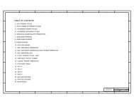
Contents<br />
Contents<br />
1.0 Introduction ...............................................................................................................................5<br />
1.1 Purpose of <strong>DSLAM</strong> <strong>Example</strong> <strong>Design</strong>....................................................................................5<br />
1.2 Scope of <strong>Example</strong> <strong>Design</strong> ....................................................................................................5<br />
1.3 Execution Environment.........................................................................................................6<br />
1.3.1 Software...................................................................................................................6<br />
1.3.2 Hardware .................................................................................................................6<br />
2.0 System Overview.....................................................................................................................7<br />
2.1 Software Partitioning.............................................................................................................8<br />
2.2 Dual Chip Data Flow...........................................................................................................10<br />
2.3 StrongARM Core Initialization.............................................................................................13<br />
2.4 Microengine Initialization ....................................................................................................13<br />
3.0 Microengine Functional Blocks.......................................................................................14<br />
3.1 Receive Microblock Group..................................................................................................14<br />
3.1.1 Initialization Microblock..........................................................................................15<br />
3.1.2 Ingress Microblock.................................................................................................15<br />
3.1.3 Transform Microblock ............................................................................................16<br />
3.1.4 Egress Microblock .................................................................................................17<br />
3.2 Receive Processor Transmit Microblock Group .................................................................19<br />
3.3 Transmit Processor Receive Microblock Group .................................................................20<br />
3.3.1 Initialization Microblock..........................................................................................20<br />
3.3.2 Ingress Microblock.................................................................................................20<br />
3.3.3 Transform Microblocks...........................................................................................21<br />
3.3.4 Egress Microblock .................................................................................................21<br />
3.4 Transmit Processor Traffic Scheduler ................................................................................21<br />
3.5 Transmit Processor Traffic Shaper .....................................................................................22<br />
3.6 Transmit Processor Traffic Transmit...................................................................................22<br />
4.0 Data and Tables......................................................................................................................22<br />
4.1 Receive Processor..............................................................................................................22<br />
4.1.1 Input Data ..............................................................................................................22<br />
4.1.2 Output Data ...........................................................................................................26<br />
4.2 Transmit Processor.............................................................................................................28<br />
4.2.1 Input Data ..............................................................................................................28<br />
4.2.2 Output Data ...........................................................................................................29<br />
4.3 Connection, Routing, and Hash Tables ..............................................................................29<br />
4.3.1 Rate Manager ........................................................................................................30<br />
4.3.1.1 Port Table Entry .....................................................................................30<br />
4.3.1.2 VC Table Entry.......................................................................................31<br />
5.0 Project Configuration / Modifying the <strong>Example</strong> <strong>Design</strong> ........................................32<br />
6.0 Testing Environment............................................................................................................32<br />
7.0 Simulation Support (Scripts, etc.) ..................................................................................32<br />
7.1 Simulation for the Receive Processor Project ....................................................................32<br />
Application Note