CIMCO CNC-Calc v2.5 User Guide
CIMCO CNC-Calc v2.5 User Guide
CIMCO CNC-Calc v2.5 User Guide

You also want an ePaper? Increase the reach of your titles
YUMPU automatically turns print PDFs into web optimized ePapers that Google loves.
www.cimco-software.com<br />
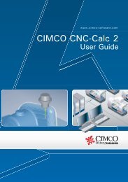
<strong>CIMCO</strong> <strong>CNC</strong>-<strong>Calc</strong> 2<br />
Tutorial
27<br />
9. Tutorial 1<br />
2D Construction<br />
This tutorial demonstrates one of many ways in which the 2-dimensional part above<br />
can be drawn in <strong>CNC</strong>-<strong>Calc</strong> v2. Since the part consists of a number of similar<br />
elements and since its part-elements are symmetrical, only a subsection of the part<br />
needs to be drawn. The rest emerges from mirroring and finally joining the mirrored<br />
elements with straight lines completes the part.<br />
This tutorial demonstrates the use of the following functions:<br />
• Draw a rectangle with a corner radius<br />
• Draw a circle with known center and radius<br />
• Draw vertical and horizontal lines from known points<br />
• Offset a circle<br />
• Make curves between elements<br />
• Delete elements<br />
• Mirror elements about lines<br />
• Join end points with straight lines<br />
• Save file with name of your own choice
28<br />
9.1. Before you start<br />
The first thing to do before drawing a new part is to set the menu parameters. Start<br />
<strong>CIMCO</strong> Edit v5 and select Setup > Show Toolbars. Make sure all toolbars are<br />
displayed as shown in the image below. Toolbars can also be displayed or hidden by<br />
right-clicking on the toolbar area.<br />
To make a new drawing you must click<br />
on <strong>CNC</strong>-<strong>Calc</strong><br />
<strong>Calc</strong> and then select New<br />
Drawing.
29<br />
The following window should now be displayed:<br />
Note<br />
If you hold the cursor over an icon a short description of its<br />
functionality will appear.<br />
You can change the colors of the drawing area by selecting Setup<br />
and then Colors from the dropdown menu.
30<br />
9.2. Draw the geometry<br />
Draw a rectangle with sides = 150, height = 100 and corner radius = 12.5<br />
Click on<br />
values:<br />
in the toolbar and enter the following<br />
First Corner X = 75<br />
First Corner Y = 50<br />
Second Corner X = -75<br />
Second Corner Y = -50<br />
Corner Radius = 12.5<br />
Click on<br />
to approve the command.<br />
Draw a circle with radius = 5 defined by its center<br />
Click on<br />
in the toolbar.<br />
Enter Circle Radius = 5<br />
Activate the snap function<br />
points).<br />
(circles center<br />
Snap to the center of the left topmost corner arc.<br />
Left-click to add the circle.
31<br />
Draw a vertical and horizontal line defined by its end point and length<br />
Activate the snap function<br />
and<br />
(midpoint of lines).<br />
(circles center points)<br />
Click on<br />
(-20.0000).<br />
and enter the following into the dialog<br />
Snap to the center of the left topmost corner arc.<br />
Click to add the vertical line.<br />
Snap to the midpoint of the topmost horizontal line.<br />
Click to add a vertical line. This will serve as a mirror line for the mirroring of our<br />
part about the Y-axis.<br />
Similar to the above draw a horizontal line with length = 20 from the same center.<br />
This time Line Length is set to 20 and next the mirror line is added from the center<br />
of the left horizontal line (the X-axis, see picture below).<br />
Offset a circle<br />
Click on<br />
in the toolbar and enter:<br />
Offset Distance = 7.5 (12.5 - 5 = 7.5).<br />
Click on the circle and select the outermost of the appearing circles.<br />
Your drawing should now look like the one below.
32<br />
Create a fillet between elements<br />
Click on<br />
in the toolbar.<br />
Enter Fillet Radius = 5.<br />
5<br />
A<br />
B<br />
Click on the circle by A and on the line by B.<br />
From the possible solutions select the part of the circle, which makes the right fillet.<br />
In the picture below you can see how it should look.<br />
Do the same by the vertical line.<br />
The topmost left part of your drawing should<br />
now look similar to the picture on the right.<br />
Click on and delete the two lines by C<br />
(The ones pointing out from the center of the<br />
circle).<br />
C
33<br />
Mirror elements about mirror lines<br />
Click on<br />
in the toolbar.<br />
First, click on the vertical mirror line.<br />
Click on all the elements, which should be mirrored (the circle and the inner corner).<br />
You can hold down the left mouse button while dragging out a window around the<br />
elements.<br />
Now do the same and mirror about the horizontal mirror line. Continue mirroring<br />
until your drawing looks similar to the one below.<br />
Click on<br />
and delete the mirror lines.
34<br />
Connect the inner elements<br />
Activate this snap function<br />
(snap to end points).<br />
Click on<br />
in the toolbar.<br />
Snap to the two arcs end points and add the remaining horizontal and vertical lines<br />
to finish the part.<br />
Your part should now look as the one below.<br />
Name the file and save it<br />
Click on Files and then select Save as from the dropdown menu. Give the file a new<br />
name and save it (the file extension is added automatically).
35<br />
10. Tutorial 2<br />
<strong>CNC</strong>-toolpaths and Face milling<br />
With <strong>CNC</strong>-<strong>Calc</strong> v2 it is possible to create toolpaths directly from the program’s<br />
geometrical drawings. Thereby calculations become more secure and programming<br />
becomes much faster compared to doing it manually. At the same time you get a big<br />
advantage since it is possible to move, copy, rotate, scale and mirror elements with<br />
the result of instant NC-code generation.<br />
This tutorial demonstrates how the 2-dimensional part above can form the basis for<br />
NC-codes for various types of machining.<br />
Note This tutorial builds upon the result from <strong>CNC</strong>-<strong>Calc</strong> v2 Tutorial 1.
36<br />
10.1. Before you start<br />
The first thing to do before drawing a new part is to set the menu parameters. Start<br />
<strong>CIMCO</strong> Edit v5 and select Setup > Show Toolbars. Make sure all toolbars are<br />
displayed as shown in the image below. Toolbars can also be displayed or hidden by<br />
right-clicking on the toolbar area.<br />
To open a drawing click on <strong>CNC</strong>-<strong>Calc</strong><br />
<strong>Calc</strong><br />
in the menu and then on Open<br />
Drawing.<br />
Alternatively the same can be achieved<br />
by clicking on the folder icon in the<br />
toolbar.<br />
Select the file from<br />
<strong>CNC</strong>-<strong>Calc</strong> <strong>Calc</strong> Tutorial 1 and click open.
37<br />
You should now see the part from <strong>CNC</strong>-<strong>Calc</strong> v2 Tutorial 1 displayed in front of you.<br />
Note<br />
If you hold the cursor over an icon, for a moment, a short description of its<br />
functionality will appear.
38<br />
10.2. Creation of Facing toolpaths<br />
To begin with select what format the<br />
NC-program should be programmed in<br />
by arrow A.<br />
Select: ISO Milling.<br />
B<br />
A<br />
Then select Generate a <strong>CNC</strong>-Toolpath<br />
for Face Milling by clicking on the icon<br />
by arrow B.<br />
Write the text FACING in the Comment<br />
field. This text will be present at the<br />
start of the final NC code for this<br />
operation. When multiple operations<br />
exist in the same NC program, it will<br />
help to locate and identify the start of<br />
each operation.<br />
Click on the outlining contour at the<br />
place indicated by arrow C.<br />
This will select the bounding contour<br />
that the facing operation will operate on.<br />
Click on Parameters by arrow D.<br />
D<br />
C<br />
Enter the following values into the dialog<br />
shown to the right.<br />
Cutter Diameter:<br />
This is the diameter of the cutter. Here it<br />
is a 30 mm Face Mill.<br />
Start Depth: This is the top of the part.<br />
End Depth: The final depth (will be<br />
corrected by Stock to Leave).<br />
Retract Height: When the operation is<br />
finished, this is the height that the tool<br />
will retract to.<br />
Roughing Stepdown: This is the<br />
maximum roughing cuts that the<br />
operation will take.
39<br />
Finish Stepdown: If Finish Cuts larger<br />
than zero, this is the cut that will be<br />
taken in each finish cut.<br />
Finish Cuts: This is the number of finish<br />
cuts that the operation will perform. If<br />
the value is left at zero, only roughing<br />
cuts will be made.<br />
Enter the following values into the<br />
dialog, which is shown to the Right.<br />
Cutting Method: This is the method used<br />
to perform the face operation. It is<br />
possible to select Zigzag, Climb or<br />
Conventional.<br />
Move Between Cuts: This is only used<br />
for the Zigzag Cutting Method, since the<br />
other methods will move free between<br />
cuts.<br />
Overlap Across: This is the amount that<br />
the mill will hang out over the side<br />
diagonal to the cutting direction.<br />
Overlap Along: This is the distance that<br />
the tool will move out over the end<br />
before the high speed loops are taken.<br />
Entry Distance: Is the distance that the<br />
tool will start out at before the actual cut<br />
is taken.<br />
Exit Distance: This is the distance the<br />
tool moves out after the final cut is<br />
taken.<br />
Facing Angle: Is the angle that the<br />
operation is performed at. An angle of<br />
zero is along the X-axis, and an angle of<br />
90 is along the Y-axis.
40<br />
Now close the parameters dialog with OK and click on Export Editor. The following<br />
screen should now be displayed.
41<br />
10.3. Inserting a Tool with Feed and Speed<br />
<strong>Calc</strong>ulator<br />
The Feed and Speed calculator is build into <strong>CNC</strong>-<strong>Calc</strong>, and it is used to insert feed<br />
and speed data into the NC program. All the data used in the calculations can<br />
normally be found in the reference material supplied by the manufacturer.<br />
In the facing example, we used a face mill that we give the following characteristics:<br />
diameter is 30mm, it has 5 flutes, a cutting feed of 0.08mm per tooth and a cutting<br />
speed of 190mm/min.<br />
In order to use the feed and speed<br />
calculator, select Feed and Speed<br />
<strong>Calc</strong>ulator for Milling Operations by<br />
clicking on the icon indicated by<br />
arrow A.<br />
Fill in the following values:<br />
Tool # lets say that the face mill have<br />
a tool number of 1.<br />
Diameter was 30mm.<br />
# Flutes: The number of flutes was 5.<br />
Feed per tooth: In this example it is set<br />
to 0.08mm.<br />
Cutting Speed: Is set to 190.<br />
The fields are linked together, so as<br />
soon as entries are made in the cutting<br />
speed field, the other fields will be<br />
updated.<br />
A<br />
B<br />
If we wanted to have RPM 2000 and a<br />
feedrate of 800 instead of the calculated<br />
2015 and 836.385, the value for the<br />
cutting speed would be updated to<br />
188.5.<br />
Change the RPM to 2000 and the<br />
feedrate to 800.<br />
Click on Export Clipboard indicated by<br />
arrow B.
42<br />
The line for the NC program is now in the clipboard, and it is ready for insertion.<br />
Change the window to the NC program, and move to the very start, by pressing<br />
Ctrl-Home.<br />
Insert the text from the clipboard, either by pressing Ctrl-v, or selecting<br />
Edit Paste from the drop down menu.<br />
The NC program should now look similar to the one below.<br />
Now save the NC program as <strong>CNC</strong>-<strong>Calc</strong> v2 Tutorial 2.NC
43<br />
11. Tutorial 3<br />
Contour milling<br />
<strong>CNC</strong>-<strong>Calc</strong> v2 can generate contour milling - with and without radius compensation.<br />
There are several machine types in <strong>CNC</strong>-<strong>Calc</strong>, but the most comonly used are ISO G-<br />
code programming and Heidenhain plain text.<br />
This tutorial demonstrates how the above 2-dimensional part can form the basis of<br />
NC-codes for various types of machining.<br />
Note This tutorial builds upon the result from <strong>CNC</strong>-<strong>Calc</strong> v2 Tutorial 1.
44<br />
11.1. Before you start<br />
The first thing to do before drawing a new part is to set the menu parameters. Start<br />
<strong>CIMCO</strong> Edit v5 and select Setup > Show Toolbars. Make sure all toolbars are<br />
displayed as shown in the image below. Toolbars can also be displayed or hidden by<br />
right-clicking on the toolbar area.<br />
To open a drawing click on <strong>CNC</strong>-<strong>Calc</strong><br />
<strong>Calc</strong><br />
in the menu and then on Open<br />
Drawing<br />
rawing.<br />
Alternatively the same can be achieved<br />
by clicking on the folder icon in the<br />
toolbar.<br />
Select the file from<br />
<strong>CNC</strong>-<strong>Calc</strong> <strong>Calc</strong> Tutorial 1 and click open.
45<br />
You should now see the part from <strong>CNC</strong>-<strong>Calc</strong> v2 Tutorial 1 displayed in front of you.<br />
Note<br />
If you hold the cursor over an icon, for a moment, a short<br />
description of its functionality will appear.
46<br />
11.2. Creation of Contour toolpaths<br />
In order to begin the creation of a NC<br />
program for the contour operation select<br />
the Generate <strong>CNC</strong>-Toolpath for Contour<br />
Milling by clicking on the icon indicated<br />
by arrow A.<br />
Write CONTOUR in the Comment field.<br />
A<br />
This text will be present at the start of<br />
the final NC program. When multiple<br />
operations exist in the same NC, it will<br />
help to locate and identify the start of<br />
each operation.<br />
B<br />
C<br />
Click on the outlining contour at the<br />
place indicated by arrow B.<br />
This highlights the outline contour, and<br />
the direction of the arrows indicate the<br />
way the tool will travel.<br />
What side the tool will machine, is<br />
controlled by the Work Side drop down<br />
box on the General tab in the parameters<br />
dialog.<br />
Click on Parameters by arrow C.<br />
Enter the values in the dialogs as shown.
47<br />
This dialog contains all the general<br />
parameters that are used for roughing and<br />
finish in both depth and side cuts.<br />
Cutter Diameter: The diameter of the tool<br />
in use.<br />
Retract Height: The height where the tool<br />
will move between contours, and where it<br />
it will stop at the end of the operation.<br />
Safe Distance: This is the distance above<br />
the part, where the feedrate will change<br />
from rapid to cutting speed.<br />
Start Depth: This is top of the stock.<br />
End Depth This is the depth where the<br />
last cut will be taken. This value is<br />
corrected by the Stock to leave Z value.<br />
Stock to Leave XY: This is the amount of<br />
stock that is left in the XY/side direction<br />
at the end of the operation (after both<br />
Roughing and Finish).<br />
Stock to leave Z: This is the amount of<br />
stock that is left in the Z/depth direction<br />
at the end of the operation (after both<br />
Roughing and Finish).<br />
Apply on Roughing Sidecuts:<br />
S<br />
If this check<br />
box is checked, the compensation type<br />
will be applied to both roughing and<br />
finish side cuts. Otherwise computer<br />
compensation is used for roughing cuts,<br />
and the selected compensation type for<br />
finish cuts.<br />
Compensation Type: This is the<br />
compensation type used for the operation.<br />
Work Side: This field determines which<br />
side of the contour the tool will pass on.<br />
Together with the selected direction of<br />
the contour, it determines if the milling<br />
type will be climb or conventional.
48<br />
Side cuts are the cuts taken in the XY<br />
direction.<br />
Use Side Cuts: If this check box is<br />
checked the operation will perform the<br />
cuts defined by the parameters.<br />
Otherwise only one cut at the final<br />
contour will be performed.<br />
Number of Passes (Roughing): This is<br />
the number of roughing side cuts in the<br />
operation.<br />
Spacing (Roughing): If more than one<br />
roughing pass is taken, this is the<br />
distance between them.<br />
Number of Passes (Finish): This is the<br />
number of finish side cuts in the<br />
operation.<br />
Spacing (Finish): This is the distance of<br />
each finish pass.<br />
Final Depth: If this check box is checked,<br />
the finish passes will only be taken at the<br />
final depth.<br />
All Depths: If this check box is checked,<br />
the finish passes will be taken at every<br />
depth.<br />
Overlap Distance: This is the distance<br />
that all the finish laps will overlap, in<br />
order to smooth the surface.
49<br />
Depth cuts are the cuts taken in the Z<br />
direction.<br />
Use Depth Cuts: If this check box is<br />
checked the operation will perform the<br />
cuts defined by the parameters.<br />
Otherwise only one cut at the final depth<br />
will be performed.<br />
Max Roughing Steps: This is the<br />
maximum cut that will be taken in a<br />
roughing cut.<br />
Use Even Depth Cuts: If this check box<br />
is checked, all the roughing passes will<br />
have the same distance. If it is left<br />
unchecked, cuts will be taken at the Max<br />
Roughing Steps distance, and any rest<br />
material will be taken with the last cut.<br />
Number of Cuts (Finish): This is the<br />
number of finish depth cuts in the<br />
operation.<br />
Steps (Finish): This is the distance of<br />
each finish pass.<br />
Linearize Helix Movements: Some<br />
machines can not make helix movements,<br />
and if this check box is checked, all helix<br />
movements will be converted to lines in<br />
the NC operation.<br />
Linearization Tolerance: When the helix<br />
is converted to lines, this will be the<br />
maximum error for the final lines.<br />
By Depth: This is only used if multiple<br />
contours are milled in the same<br />
operation. If it is selected the cut on each<br />
depth will be performed on all contours,<br />
before any cuts are made at a new depth.<br />
By Contour: If is selected one contour<br />
will be milled from start to finish, before<br />
the next contour is worked upon.
50<br />
Lead in/out parameters describe the way<br />
the tool will approach the contour at the<br />
start/end of the roughing, and for each<br />
finish pass.<br />
The use of lead in/out is optional when<br />
the compensation is set to computer or<br />
none. It is however mandatory, when any<br />
compensation is performed by the<br />
controller.<br />
Use Lead In/Out Parameters: Enables or<br />
disables the lead in and out.<br />
Use Line: Enable or disables the lead<br />
in/out lines.<br />
Line Length: Is the length of the lead<br />
in/out line.<br />
Perpendicular: If it is selected the line<br />
will be perpendicular to the following<br />
element for lead in, and the previous<br />
element for lead out.<br />
Parallel: If it is selected the line will be<br />
parallel to the following element for lead<br />
in, and the previous element for lead out.<br />
Use Arc: Enable or disables the lead<br />
in/out arcs.<br />
Radius: Is the radius of the lead in/out<br />
arc.<br />
Sweep: Is the sweep angle of the lead<br />
in/out arc.<br />
The two arrows in the middle of the<br />
dialog are used to copy all values from<br />
lead in to out, and the other way.
51<br />
Now close the parameters dialog with OK and click on Export Clipboard. The NC<br />
operation is now in the clipboard, and it is ready for insertion.<br />
Change the window to the NC program, and move to the very end, by pressing Ctrl-<br />
End. Insert the text from the clipboard, either by pressing Ctrl-v, or selecting Edit <br />
Paste from the drop down menu.<br />
The NC program in the Editor now consists of two operations and currently they are<br />
both made with the same tool. Now we need to insert a new tool for the contour<br />
operatio<br />
11.3. Inserting a Tool with<br />
Feed and Speed <strong>Calc</strong>ulator<br />
Follow the steps from the previous tutorial for the Feed and Speed on page 41.<br />
Instead of the values used there, use the following values:<br />
Tool #: 2<br />
Diameter (D) in mm: 10<br />
# Flutes (Z): 4<br />
Feed per tooth (Sz) in mm: 0.06<br />
Cutting Speed (V) in mm/min: 175<br />
Now the last two values have been calculated and inserted in the dialog.<br />
They should be:<br />
RPM: 5570<br />
Feedrate (F) in mm/min: 1336.9015<br />
Correct the RPM to 5500 and then Feedrate (F) in mm/min: to 1320.<br />
Now the Feed and Speed dialog should look like the one below:
52<br />
Click on Export Clipboard to copy the generated line to the clipboard.<br />
Change to the NC program in the editor. After the contour operation was copied to<br />
the editor, the cursor is at the very end of the program. In order to insert the tool<br />
line from the clipboard, we must locate the start of the contour operation. Since the<br />
comment CONTOUR was inserted, it is easy to locate the start of the operation.<br />
Find the text CONTOUR, either by pressing Ctrl-f, or selecting Edit Find from<br />
the drop down menu.<br />
Go to the start of the comment line and insert the text from the clipboard.<br />
The NC program should now look like the following.<br />
Save the NC program as <strong>CNC</strong>-<strong>Calc</strong> v2 Tutorial 3.NC
53<br />
12. Tutorial 4<br />
Pocket milling<br />
<strong>CNC</strong>-<strong>Calc</strong> v2 can generate pocket milling. There are several machine types in <strong>CNC</strong>-<br />
<strong>Calc</strong>, but the most commonly used are ISO G-code programming and Heidenhain<br />
plain text.<br />
This tutorial demonstrates how the above 2-dimensional part can form the basis of<br />
NC-codes for various types of machining.<br />
Note This tutorial builds upon the result from <strong>CNC</strong>-<strong>Calc</strong> v2 Tutorial 1.
54<br />
12.1. Before you start<br />
The first thing to do before drawing a new part is to set the menu parameters. Start<br />
<strong>CIMCO</strong> Edit v5 and select Setup > Show Toolbars. Make sure all toolbars are<br />
displayed as shown in the image below. Toolbars can also be displayed or hidden by<br />
right-clicking on the toolbar area.<br />
To open a drawing click on <strong>CNC</strong>-<strong>Calc</strong><br />
<strong>Calc</strong><br />
in the menu and then on Open<br />
Drawing.<br />
Alternatively the same can be achieved<br />
by clicking on the folder icon in the<br />
toolbar.<br />
Select the file from<br />
<strong>CNC</strong>-<strong>Calc</strong> <strong>Calc</strong> Tutorial 1 and click open.
55<br />
You should now see the part from <strong>CNC</strong>-<strong>Calc</strong> v2 Tutorial 1 displayed in front of you.<br />
Note<br />
If you hold the cursor over an icon, for a moment, a short<br />
description of its functionality will appear.
56<br />
12.2. Creation of Pocket toolpaths<br />
In order to begin the create a NC<br />
program for the pocket operation select<br />
the Generate a <strong>CNC</strong>-Toolpath for Pocket<br />
Milling by clicking on the icon indicated<br />
by arrow A.<br />
Write the text POCKET in the<br />
Comment field.<br />
This text will be present at the start of<br />
the final NC program. When multiple<br />
operations exist in the same NC, it will<br />
help to locate and identify the start of<br />
each operation.<br />
A<br />
C<br />
B<br />
Click on the inner contour at the place<br />
indicated by arrow B. This will highlight<br />
the inner contour.<br />
Click on Parameters by arrow C.<br />
This dialog contains all the general<br />
parameters that are used for roughing<br />
and finish in both depth and side cuts.<br />
Enter the values in the various dialogs<br />
as shown.<br />
Cutting Diameter: The diameter of the<br />
used tool.<br />
Retract Height: The height where the<br />
tool will move between contours, and<br />
where it it will stop at the end of the<br />
operation.<br />
Safe Distance: This is the distance above<br />
the part, where the feedrate will change<br />
from rapid to cutting speed.<br />
Start Depth: This is top of the stock.<br />
End Depth<br />
This is the depth where the<br />
last cut will be taken. This value is
57<br />
corrected by the Stock to leave Z value.<br />
Stock to Leave XY: This is the amount<br />
of stock that is left in the XY/side<br />
direction at the end of the operation<br />
(after both Roughing and Finish).<br />
Stock to leave Z: This is the amount of<br />
stock that is left in the Z/depth<br />
direction at the end of the operation<br />
(after both Roughing and Finish).<br />
Compensation Type: This is<br />
compensation type used for the<br />
operation.<br />
Conventional: When checked, the<br />
operation will be generated using<br />
conventional milling.<br />
Climb: When checked, the operation will<br />
be generated using climb milling.<br />
Side cuts are the cuts taken in the XY<br />
direction.<br />
Use Side Cuts: If this check box is<br />
checked the operation will perform the<br />
cuts defined by the parameters.<br />
Otherwise only one cut at the final<br />
contour will be performed.<br />
Max Roughing Spacing: This is the<br />
maximum side step over used in the<br />
roughing of the part.<br />
Number of Passes (Finish): This is the<br />
number of finish side cuts in the<br />
operation.<br />
Spacing (Finish): This is the distance of<br />
each finish pass.<br />
At Final Depth: If this check box is<br />
checked, the finish passes will only be<br />
taken at the final depth.
58<br />
At All Depths: If this check box is<br />
checked, the finish passes will be taken at<br />
every depth.<br />
Overlap Distance: This is the distance<br />
that all the finish laps will overlap, in<br />
order to smooth the surface.<br />
Roughing Smoothing: This slider controls<br />
the amount of smoothing used. The<br />
higher the value (rightmost), the<br />
smoother the resulting toolpath will be.<br />
Depth cuts are the cuts taken in the Z<br />
direction.<br />
Use Depth Cuts: If this check box is<br />
checked the operation will perform the<br />
cuts defined by the parameters.<br />
Otherwise only one cut at the final depth<br />
will be performed.<br />
Max Roughing Steps: This is the<br />
maximum cut that will be taken in a<br />
roughing cut.<br />
Use Even Depth Cuts: If this check box<br />
is checked, all the roughing passes will<br />
have the same distance. If it is left<br />
unchecked, cuts will be taken at the Max<br />
Roughing Steps distance, and any rest<br />
material will be taken with the last cut.<br />
Number of Cuts (Finish): This is the<br />
number of finish depth cuts in the<br />
operation.<br />
Steps (Finish): This is the distance of<br />
each finish pass.<br />
Linierize Helix Movements: Some<br />
machines can not make helix movements,<br />
and if this check box is checked, all helix<br />
movements will be converted to lines in<br />
the NC operation.
59<br />
Linearization Tolerance: When the helix<br />
is converted to lines, this will be the<br />
maximum error for the final lines.<br />
By Depth: This is only used if multiple<br />
pockets are milled in the same operation.<br />
If it is selected the cut at each depth will<br />
be performed on all pockets, before any<br />
cuts are made at a new depth.<br />
By Pocket: If this is selected one pocket<br />
will be milled from start to finish, before<br />
the next pocket is worked upon.<br />
The entry strategies define how the tool<br />
cuts from one Z level to the next.<br />
Plunge: When this is selected, the tool<br />
will move straight down.<br />
Ramp: With the ramp entry the tool<br />
moves down to the Ramp Clearance<br />
C<br />
above the part. Then it makes a ramp<br />
movement with the length Ramp Length<br />
and the angle Ramp Angle.<br />
Helix Entry: Moves down to Helix<br />
Clearance above the part. Then it will<br />
spiral down with the angle Helix Angle in<br />
a circular movement with a radius<br />
between Helix Diameter and Minimum<br />
Helix Diameter. How big the actual<br />
diameter will be depends on the<br />
geometry,
60<br />
Lead in/out parameters describe the way<br />
that the tool will approach the contour at<br />
the start/end of the roughing, and for<br />
each finish pass.<br />
The use of lead in/out is optional when<br />
the compensation is set to computer or<br />
none. It is however mandatory, when any<br />
compensation is performed by the<br />
controller.<br />
Use Lead In/Out Parameters: Enables or<br />
disables the lead in and out.<br />
Use Line: Enable or disables the lead<br />
in/out lines.<br />
Line Length: Is the length of the lead<br />
in/out line.<br />
Perpendicular: If it is selected the line<br />
will be perpendicular to the following<br />
element for lead in, and the previous<br />
element for lead out.<br />
Parallel: If it is selected the line will be<br />
parallel to the following element for lead<br />
in, and the previous element for lead out.<br />
Use Arc: Enable or disables the lead<br />
in/out arcs.<br />
Radius: Is the radius of the lead in/out<br />
arc.<br />
Sweep: Is the sweep angle of the lead<br />
in/out arc.<br />
The two arrows in the middle of the<br />
dialog are used to copy all values from<br />
lead in to out, and the other way.
61<br />
Now close the parameters dialog with OK and click on Export Clipboard. The NC<br />
operation is now in the clipboard, and is ready for insertion.<br />
Change the window to the NC program, and move to the very end, by pressing Ctrl-<br />
End. Insert the text from the clipboard, either by pressing Ctrl-v, or selecting Edit <br />
Paste from the drop down menu.<br />
The NC program in the Editor now consists of three operations, and since we use the<br />
same tool for the contour and pocket operation we will not insert a tool in front of<br />
the pocket operation.<br />
Now save the program the NC program as <strong>CNC</strong>-<strong>Calc</strong> v2 Tutorial 4.NC
62<br />
13. Tutorial 5<br />
Backplot in the Editor<br />
One of the advantages of running <strong>CNC</strong>-<strong>Calc</strong> inside <strong>CIMCO</strong> Edit v5 is that the editor<br />
can be used to manipulate and backplot the NC programs generated in <strong>CNC</strong>-<strong>Calc</strong>.<br />
In the following we will setup the backplot, and verify the program.<br />
13.1. Before you start<br />
The first thing to do before drawing a new part is to set the menu parameters. Start<br />
<strong>CIMCO</strong> Edit v5 and select Setup > Show Toolbars. Make sure all toolbars are<br />
displayed as shown in the image below. Toolbars can also be displayed or hidden by<br />
right-clicking on the toolbar area.
63<br />
To open a NC Program click the<br />
open program icon indicated by<br />
arrow A.<br />
A<br />
This will open the Open File dialog,<br />
where the file you want to open can<br />
be selected.<br />
Please select the file from the last<br />
tutorial and click open.<br />
You should now see the NC program from the last tutorial.
64<br />
13.2. The first backplot<br />
When you have the NC program loaded in the editor, it is possible to backplot it.<br />
Click on the backplot icon in the floating<br />
toolbar indicated by arrow A. This will<br />
open the backplot window.<br />
This window can also be opened by<br />
Backplot Backplot Window in the<br />
dropdown menues.<br />
Now the screen should look like the one below.<br />
Here the toolpath is shown. It looks OK, but it can be configured to look a lot more<br />
like the final part. To do this we need to define the individual tools, and the stock.
65<br />
13.3. Backplot tool setup.<br />
The following steps will show you how to setup the tools used in the backplot.<br />
Click on the Tool Setup icon in the<br />
floating toolbar indicated by arrow A.<br />
This will open the backplot Tool<br />
definition window.<br />
A<br />
When backplot persed the NC program,<br />
it detected, that there where two tools<br />
used.<br />
Since these tools have not been defined,<br />
the screen will look like the one to the<br />
left.<br />
In order to backplot the program<br />
correctly, we need to define these two<br />
tools.<br />
By changing the type and the diameter<br />
of the tools, we can create the correct<br />
setup.<br />
Please select and enter the values shown<br />
on the picture on the right.<br />
These are the same tool values that was<br />
used when the NC programs was<br />
generated in <strong>CNC</strong>-<strong>Calc</strong>.<br />
Now exit the configuration dialog with<br />
OK.
66<br />
After the tools have been configured, the screen should look like the one below. Try<br />
to find the tool changes and verify that the tool does endeed change when a tool<br />
change is encountered in the NC program.
67<br />
13.4. Backplot Stock setup.<br />
The following steps will show you how to setup the stock used in the backplot.<br />
Click on the Solid Setup icon in the<br />
floating toolbar indicated by arrow A.<br />
This will open the backplot Solid Setup<br />
window.<br />
A<br />
The default values shown in the dialog<br />
are based on the cutting moves in the NC<br />
program.<br />
Since the tool moves down in cutting<br />
speed, the Z-max will nearly always be<br />
too big.<br />
The same is the case for the facing<br />
operation. That will give a too large<br />
stock along both the X- and Y- axis.<br />
From the facing operation we know that<br />
the top of the stock should be Z:2.00.<br />
From the drawing we know that the<br />
values of the corners are (0.00, 0.00) and<br />
(150.00, 100.00).<br />
We now make the stock 2mm larger<br />
along X- and Y-axis, so the values will be<br />
the ones shown in the dialog on the right.<br />
Please enter these and exit the dialog<br />
with OK.
68<br />
Now everything has been configured, and the backplot can now be used to verify the<br />
operations. The screen should now look like the one shown below.
69<br />
14. Tutorial 6<br />
Drilling<br />
<strong>CNC</strong>-<strong>Calc</strong> v2 can generate codes for drilling in either canned cycles or as longhand.<br />
There are several machine types in <strong>CNC</strong>-<strong>Calc</strong>, but the most commonly used are ISO<br />
G-code programming and Heidenhain plain text.<br />
14.1. Before you start<br />
The first thing to do before drawing a new part is to set the menu parameters. Start<br />
<strong>CIMCO</strong> Edit 5 and select Setup > Show Toolbars. Make sure all toolbars are<br />
displayed as shown in the image below. Toolbars can also be displayed or hidden by<br />
right-clicking on the toolbar area.<br />
To open a drawing click on <strong>CNC</strong>-<br />
<strong>Calc</strong> in the menu and then on Open<br />
Drawing.<br />
Alternatively the same can be<br />
achieved by clicking on the folder<br />
icon in the toolbar.
70<br />
Select the file from<br />
<strong>CNC</strong>-<strong>Calc</strong> <strong>Calc</strong> Tutorial 1 and click open.<br />
You should now see the part from <strong>CNC</strong>-<strong>Calc</strong> v2 Tutorial 1 displayed in front of you.<br />
Note<br />
If you hold the cursor over an icon, for a moment, a short<br />
description of its functionality will appear.
71<br />
14.2. Generate a drill cycle<br />
To begin with select what format the<br />
NC-program should be programmed in<br />
by arrow A.<br />
Select: ISO - Mill.<br />
Then select Generate a drill Cycle by<br />
clicking on the icon by arrow B.<br />
Fill in the following values:<br />
Name: DRILL<br />
Machine Zero X: 0<br />
Machine Zero Y: 0<br />
Click on Drill Parameters, which<br />
displays the window shown below.<br />
Please enter these parameters for this drilling operation. Notice that in this example<br />
it makes no Difference if we have selected Incremental or Absolute Safe Distance and<br />
Depth, since these incremental values refer to the Reference Plane, which is 0.
72<br />
For the selection of the location of the holes several options are available:<br />
1. Select each hole location with the cursor. In order to get the correct hole<br />
center for circles and arcs, the snap to center should be used<br />
2. Select the actual circle or arc. This will create a new hole location, at the<br />
center of the circle/arc.<br />
3. Use window selection with or without filter. If the filter is used it is possible<br />
to limit the selection to cirles or arcs in different ranges.<br />
In the following we will use the filter to select the corner holes, but not any of the<br />
arcs.<br />
By setting up the filter as shown, we will<br />
limit the window selection to include only<br />
circles in the range from 0 to 10 in<br />
diameter.<br />
Now enable the Use Selection Filter in the lefthand pane, and then make a window<br />
selection, that includes the entire drawing.<br />
When this selection is made, only the four corner holes should be selected.<br />
Click on Export Editor. The following program is displayed in the editor.<br />
(DRILL)<br />
G00 X12.5 Y87.5<br />
G00 Z10.0<br />
G83 X12.5 Y87.5 Z-7.0 R2.0 Q1.0 F200.0<br />
X137.5<br />
Y12.5<br />
X12.5<br />
G80<br />
The order of operation can then be changed by clicking on Reorder Circ and<br />
Reorder Rect in the dialog.
73<br />
15. Tutorial 7<br />
Milling of Letters<br />
This tutorial demonstrates how a 2-dimensional text can be used as the basis for an<br />
NC program milling letters and numbers.<br />
15.1. Before you start<br />
When a new part is to be machined you should first make sure to display the<br />
toolbars you need. Start <strong>CIMCO</strong> Edit 5, 5 click the dropdown menu Setup, and then<br />
click Show Toolbars. Now select the needed toolbars as shown below. Clicking an<br />
already selected toolbar in the list deselects it.<br />
Notice<br />
This menu can also be reached by right-clicking any toolbar<br />
already in view.
74<br />
Once the toolbars have been selected you are ready to start on a new drawing. To do<br />
this click on the icon or click on <strong>CNC</strong>-<strong>Calc</strong><br />
<strong>Calc</strong> in the menu, and then on New<br />
Drawing.<br />
In this tutorial we will try to machine a single line of text composed of letters and<br />
numbers. For this example we have chosen the text “<strong>CIMCO</strong> 123”.<br />
Normal upper and lower case letters, numbers, and characters can be entered when<br />
the icon<br />
is clicked.<br />
The dialog Text Entry appears to the left. In the input field at the bottom named<br />
text, enter the text that will be machined. In this example “<strong>CIMCO</strong> 123”.<br />
In addition to the text five additional parameters are needed to specify start point,<br />
baseline angle, letter distance and letter height. Fill in the fields with the values from<br />
below.<br />
X coordinates of the text start point:<br />
Y coordinates of the text start point:<br />
Angle of the text baseline:<br />
Distance between letters:<br />
Letter height:<br />
-68<br />
-30<br />
15.0<br />
6.0<br />
25.0<br />
(mm)<br />
(mm)<br />
(deg.)<br />
(mm)<br />
(mm)<br />
When you are done entering text and values click the blue check mark button<br />
the bottom right of the dialog to accept.<br />
at
75<br />
Your screen should now look like the following.<br />
The text is now showing in the drawing and its geometry can now be used for<br />
generating the toolpaths.<br />
Select the file type (NC Format) for our example letter milling program (e.g. ISO<br />
Milling).
76<br />
Select the feature Letter Milling by clicking the <strong>CNC</strong>-<strong>Calc</strong><br />
<strong>Calc</strong> menu, then Millng<br />
Operations, Mill Letters, or select the corresponding icon from the Milling<br />
Operations toolbar.<br />
The dialog Letter Milling will appear on the left side of the screen as shown above.<br />
Further, you should also click on the Parameters button to define e.g. retract height<br />
over the part surface. For this example we chose a 2 mm. retract height, see below.
77<br />
Besides Retract Height you can choose if retracts should be carried out in rapid or<br />
feed mode. Once finished click OK to close the Parameters dialog..<br />
Now use window selection to select the text you want to mill. On the drawing leftclick<br />
one corner, hold down the mouse button and drag diagonally. When the desired<br />
text is framed, release the button. The frame disappears and the text will have<br />
turned yellow to indicate that it has been selected.<br />
Next click on the Export Editor button, and this will show the NC codes for<br />
machining the text in the Editor.
78<br />
To verify the generated toolpath we must simulate it using the integrated Graphical<br />
Backplot. To open the backplot window click on Backplot in the menu and then on<br />
Backplot Window as shown below.<br />
At the bottom right of the backplot window, start the simulation by clicking<br />
Start/Stop Simulation indicated by the icon .<br />
Simulation speed and direction is infinitely variable both forwards and backwards.<br />
This is controlled by dragging the slider either to the left or to the right where right<br />
is forward.<br />
If you want to verify a certain operation in the NC program, simply click on a line of<br />
the NC code to the left. The simulation tool will immediately position itself on the<br />
corresponding place in the simulation. You can move the tool one line at a time using<br />
the up and down arrow keys on your keyboard, or skip through the code a page at a<br />
time using PageUp and PageDown.
79<br />
Your screen should now present “<strong>CIMCO</strong> 123” in the following way.<br />
Notice the rapid moves, indicated by the yellow lines, retracting to the level we<br />
defined using the Parameters dialog.<br />
The example text milling program “<strong>CIMCO</strong> 123” can be used as subprogram to<br />
another program by simple cut-and-paste, but can also be completed as an<br />
independent program, providing it is supplied with the code lines for Program<br />
Start/Program Stop, Tool Change, and Feed/Speed, which you can quickly add<br />
either manually or with the Macro function in <strong>CIMCO</strong> Edit 5.<br />
Important notice<br />
The final execution of the program depends to a high degree of the applied macro<br />
programs. It is also important that the correct set-up of <strong>CNC</strong>-<strong>Calc</strong> is used for each<br />
machine/control.<br />
It is very important to verify/simulate the programs before they are executed on a<br />
machine. Please pay special attention to the movements in the Z axis, and make sure<br />
that they run with the required feed and rapid move speed.
80<br />
16. Tutorial 8<br />
Milling of TrueType Letters<br />
This tutorial demonstrates how a 2-dimensional TrueType text can provide the basis<br />
for an NC program milling letters and numbers.<br />
16.1. Before you start<br />
When a new part is to be machined you should first make sure to display the<br />
toolbars you need. Start <strong>CIMCO</strong> Edit 5, 5 click the dropdown menu Setup, and then<br />
click Show Toolbars. Now select the needed toolbars as shown below. Clicking on an<br />
already selected toolbar in the list deselects it.<br />
Error! Not a valid embedded object.<br />
Notice<br />
This menu can also be reached by right-clicking any toolbar<br />
already in view.
81<br />
To start a new drawing, either click on the icon<br />
menu, and then on New Drawing.<br />
or click on <strong>CNC</strong>-<strong>Calc</strong><br />
<strong>Calc</strong> in the<br />
In this tutorial we will machine a single line of TrueType text composed of letters<br />
and numbers. For this example we have chose the text <strong>CIMCO</strong> 456 .<br />
To create TrueType letters, numbers, and characters select the function Create<br />
TrueType text in drawing by clicking on .<br />
The dialog Text Entry appears to the left. Enter the coordinates for the starting<br />
point of the text, the angle (relative to the horizontal axis) of the text baseline, and<br />
the height of the letters.<br />
X coordinates of the text start point:<br />
Y coordinates of the text start point:<br />
Angle of the text baseline:<br />
Letter height:<br />
-68<br />
-30<br />
30.0<br />
25.0<br />
(mm)<br />
(mm)<br />
(deg.)<br />
(mm)
82<br />
In the bottom field you write the text (here “<strong>CIMCO</strong> 456”) to be milled with<br />
TrueType letters.<br />
Next select the font type and font size by opening the font dialog by clicking on the<br />
button Select Font. End this dialog by clicking ’OK’. As a result of the changes you<br />
make in the font dialog the look of the text changes. You can enter the font dialog<br />
again until you are satisfied with the layout.<br />
When done click on the blue check mark button to insert<br />
the text. This is<br />
important since otherwise the text will disappear once you start doing other things.<br />
With parameters, text, and font defined your screen should look like the following.<br />
Depending on your choice of font this might vary.
83<br />
The geometry is now finished and can be used for the generation of toolpaths.<br />
Now select the file type (NC format) for the TrueType text mill program<br />
(e.g. ISO Milling).<br />
From the <strong>CNC</strong>-<strong>Calc</strong><br />
<strong>Calc</strong> menu, select Milling Operations and Mill TrueType letters, or<br />
click the corresponding icon on the toolbar.
84<br />
The Letter Milling dialog has now appeared to the left. Click on the Parameters<br />
button.
85<br />
The TrueType Text Milling Parameters dialog appears. Check the Mill Outline<br />
checkbox at the top and fill in the rest of the fields as shown below. Click ’OK’ when<br />
done.<br />
Use window selection to select the letters to mill. This is done by left-clicking in the<br />
upper-left corner of the drawing. Now hold the mouse button down and drag the<br />
cursor to the lower-right corner and release the mouse button. Click on the button<br />
Show Toolpath. Now the screen will show the generated toolpaths which is layed out<br />
directly over the outline of the text (it might be hard to see). Finally click on the<br />
button Export Editor.<br />
Now the NC-codes for the machining are shown in the editor. Use the Graphical<br />
Backplot to simulate and verify the toolpaths. To start the backplot click on the<br />
Backplot menu and then on Backplot Window.<br />
Use the buttons in the lower-right corner of the window to control the simulation<br />
speed and direction. By clicking on a line in the NC-code to the left the tool will<br />
jump to that position in the simulation. The up and down key moves the line<br />
selection to the previous or next line, and the tool will be moved acordingly.
86<br />
16.2. Pocket milling letters<br />
The toolpath generated from the text look like a contour operation formed by the<br />
outlines of the letters and numbers. The area inside these contours - inside the letters<br />
- can be milled like a special pocket milling operation. The rest of this tutorial will<br />
show you how to do this.<br />
1. Return to the drawing by clicking the tab marked A in Figure 9.11 below.<br />
2. Click on the button New marked B, and select the letters for the operation.<br />
3. Click the button Parameters marked C.<br />
4. Insert the new parameters as shown below (remember to check the 5. checkbox<br />
Mill Interior).
87<br />
5. Window select the text.<br />
6. Click on Show Toolpath marked D - the generated toolpaths will now be shown on<br />
the screen.<br />
7. Click the button Export Editor. Now the NC-codes for the machining are shown in<br />
the editor.<br />
Simulate the program to verify the toolpath the same way we did earlier in this<br />
tutorial.
88<br />
Verifying the toolpaths using the integrated Backplot.<br />
It is possible to generate toolpaths with both Mill Interior and Mill Outline selected<br />
under Parameters. This will create both the pocket operation on the inside, and the<br />
milling of the contours.<br />
The example program “<strong>CIMCO</strong> 456” can be used as subprogram to another program<br />
by simple cut-and-paste, but can also be completed as an independent program,<br />
providing it is supplied with the code lines for Program Start/Program Stop, Tool<br />
Change, and Feed/Speed, which you can quickly add either manually or with the<br />
Macro function in <strong>CIMCO</strong> Edit 5.<br />
Important notice<br />
The final execution of the program depends to a high degree of the applied macro<br />
programs. It is also important that the correct set-up of <strong>CNC</strong>-<strong>Calc</strong> is used for each<br />
machine/control.<br />
It is very important to verify/simulate the programs before they are executed on a<br />
machine. Please pay special attention to the movements in the Z axis, and make sure<br />
that they run with the required feed and rapid move speed.