U.S. DEPARTMENT OF TRANSPORTATION - SaferCar.gov
U.S. DEPARTMENT OF TRANSPORTATION - SaferCar.gov
U.S. DEPARTMENT OF TRANSPORTATION - SaferCar.gov

You also want an ePaper? Increase the reach of your titles
YUMPU automatically turns print PDFs into web optimized ePapers that Google loves.
TP-P572-U-00<br />
CHECK SHEET NO. A5 (Continued)<br />
THORAX - RIB DROP TEST (S572.185(b))<br />
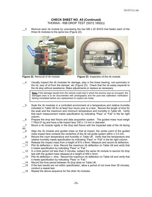
__3<br />
Remove each rib module by unscrewing the two M8 x 20 SHCS that fasten each of the<br />
three rib modules to the spine box (Figure 22).<br />
Figure 22. Removal of rib module<br />
Figure 23. Inspection of the rib module<br />
__4<br />
Visually inspect the rib modules for damage, play in the linear bearing, non-symmetry in<br />
the rib, loss of oil from the damper, etc (Figure 23). Check that the rib easily expands to<br />
the rib stop without assistance. Make adjustments or replace as necessary.<br />
Note: If the damage results from the vehicle crash test in which the dummy was an occupant, the<br />
damaged area is to be documented with photography and the post test calibration verification<br />
testing completed before any replacement or repairs are made.<br />
__5 Soak the rib modules in a controlled environment at a temperature and relative humidity<br />
indicated in Table U6 for at least four hours prior to a test. Record the length of time for<br />
the soak and the maximum and minimum temperature and humidity in Table U6. Verify<br />
that each measurement meets specification by indicating “Pass” or “Fail” in the far right<br />
column.<br />
__6 Prepare the drop test fixture and data acquisition system. The guided mass must weigh<br />
7.78±0.01 kg and have a flat impact face 150 ± 1.0 mm in diameter.<br />
__7 Mount a rib module rigidly in the drop test fixture with the impacted side of the rib facing<br />
up.<br />
__8 Align the rib module and guided mass so that at impact, the center point of the guided<br />
mass impact face contacts the centerline of the rib rail guide system within ± 2.5 mm.<br />
__9 Record the room temperature and humidity in Table U6. Verify that the temperature and<br />
relative humidity meets specification by indicating “Pass” or “Fail” in the far right column.<br />
__10 Release the impact mass from a height of 815 ± 8mm. Measure and record rib deflection.<br />
__11 Plot rib deflection v. time. Record the maximum rib deflection on Table U6 and verify that<br />
it meets specification by indicating “Pass” or “Fail.”<br />
__12 In a time period not less than 5 minutes, subject the same rib module to second rib drop<br />
test with the guided mass released at a height of 459 ± 5mm.<br />
__13 Plot rib deflection v. time. Record the maximum rib deflection on Table U6 and verify that<br />
it meets specification by indicating “Pass” or “Fail.”<br />
__14 Record the time period between rib drop tests on Table U6.<br />
__15 If the test results are not within specification, allow a period of not more than 30 minutes,<br />
conduct a repeat test.<br />
__16 Repeat the above sequence for the other rib modules<br />
-26-