- Page 1 and 2:
Rev. 09/19/2012 SEPTEMBER 2012 U.S.
- Page 3 and 4:
SINCAP MDB LABORATORY TEST PROCEDUR
- Page 5 and 6:
SINCAP MDB LABORATORY TEST PROCEDUR
- Page 7 and 8:
SINCAP MDB - 2 1. PURPOSE AND APPLI
- Page 9 and 10:
SINCAP MDB - 4 2.3. TEST VEHICLE AS
- Page 11 and 12:
SINCAP MDB - 6 schedule in cases of
- Page 13 and 14:
SINCAP MDB - 8 (10) The position of
- Page 15 and 16:
SINCAP MDB - 10 Figure 2 - Typical
- Page 17 and 18:
SINCAP MDB - 12 D. A written calibr
- Page 19 and 20:
SINCAP MDB - 14 before the MDB cont
- Page 21 and 22:
SINCAP MDB - 16 shows not only curt
- Page 23 and 24:
SINCAP MDB - 18 (2) Measure the dis
- Page 25 and 26:
SINCAP MDB - 20 D. BARRIER PHOTOGRA
- Page 27 and 28:
SINCAP MDB - 22 NOTE: The test labo
- Page 29 and 30:
SINCAP MDB - 24 9.8 STILL PHOTOGRAP
- Page 31 and 32:
SINCAP MDB - 26 No. 050 - Post-Test
- Page 33 and 34:
SINCAP MDB - 28 NOTE: The numbering
- Page 35 and 36:
SINCAP MDB - 30 (1) NHTSA Number (s
- Page 37 and 38:
SINCAP MDB - 32 H. CALCULATION OF V
- Page 39 and 40:
SINCAP MDB - 34 NOTE: The “As Tes
- Page 41 and 42: SINCAP MDB - 36 Figure 9 - Moving D
- Page 43 and 44: SINCAP MDB - 38 (1) With the seat
- Page 45 and 46: SINCAP MDB - 40 (6) If the seat and
- Page 47 and 48: SINCAP MDB - 42 seat controls the f
- Page 49 and 50: SINCAP MDB - 44 combined cable bund
- Page 51 and 52: SINCAP MDB - 46 NR NB Nose to Rim -
- Page 53 and 54: SINCAP MDB - 48 A B C D E F G H I J
- Page 55 and 56: SINCAP MDB - 50 C. MOVING DEFORMABL
- Page 57 and 58: SINCAP MDB - 52 A. MDB Centerline t
- Page 59 and 60: SINCAP MDB - 54 12.9 REMOVAL OF TES
- Page 61 and 62: SINCAP MDB - 56 F. TEST REPORT No t
- Page 63 and 64: SINCAP MDB - 58 M. The Contractor m
- Page 65 and 66: SINCAP MDB - 60 13.4 NOTIFICATION O
- Page 67 and 68: SINCAP MDB - 62 E. DRAFT TEST REPOR
- Page 69 and 70: SINCAP MDB - 64 H. DELIVERABLE SCHE
- Page 71 and 72: U.S. DEPARTMENT OF TRANSPORTATION T
- Page 73 and 74: List of Figures TP-P572-U-00 Figure
- Page 75 and 76: TP-P572-U-00 1. PURPOSE AND APPLICA
- Page 77 and 78: TP-P572-U-00 8. CALIBRATION AND TES
- Page 79 and 80: TP-P572-U-00 10. PRETEST REQUIREMEN
- Page 81 and 82: TP-P572-U-00 10. PRETEST REQUIREMEN
- Page 83 and 84: TP-P572-U-00 14. CHECK SHEETS CHECK
- Page 85 and 86: TP-P572-U-00 CHECK SHEET NO. U1 (Co
- Page 87 and 88: TP-P572-U-00 CHECK SHEET NO. U2 HEA
- Page 89 and 90: TP-P572-U-00 CHECK SHEET NO. U2 (Co
- Page 91: TP-P572-U-00 CHECK SHEET NO. U2 (Co
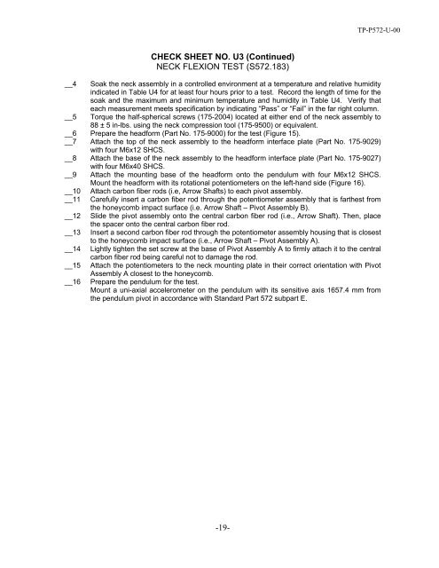
- Page 95 and 96: TP-P572-U-00 CHECK SHEET NO. U3 (Co
- Page 97 and 98: TP-P572-U-00 CHECK SHEET NO. U4 SHO
- Page 99 and 100: TP-P572-U-00 CHECK SHEET NO. U5 RIB
- Page 101 and 102: TP-P572-U-00 CHECK SHEET NO. U5 (Co
- Page 103 and 104: TP-P572-U-00 CHECK SHEET NO. U6 (Co
- Page 105 and 106: TP-P572-U-00 CHECK SHEET NO. U7 ABD
- Page 107 and 108: TP-P572-U-00 CHECK SHEET NO. U7 (Co
- Page 109 and 110: TP-P572-U-00 CHECK SHEET NO. U8 (Co
- Page 111 and 112: TP-P572-U-00 CHECK SHEET NO. U9 (Co
- Page 113 and 114: TP-P572-U-00
- Page 115 and 116: TP-P572-V-00 Feb 2011 U.S. DEPARTME
- Page 117 and 118: TP-P572-V-00 List of Figures Figure
- Page 119 and 120: TP-P572-V-00 List of Tables Table V
- Page 121 and 122: TP-P572-V-00 3. SECURITY….Continu
- Page 123 and 124: TP-P572-V-00 9. PHOTOGRAPHIC DOCUME
- Page 125 and 126: TP-P572-V-00 10. PRETEST REQUIREMEN
- Page 127 and 128: TP-P572-V-00 14. CHECK SHEETS CHECK
- Page 129 and 130: TP-P572-V-00 CHECK SHEET NO. V1 (Co
- Page 131 and 132: TP-P572-V-00 CHECK SHEET NO. V2 HEA
- Page 133 and 134: TP-P572-V-00 CHECK SHEET NO. V2 (Co
- Page 135 and 136: TP-P572-V-00 CHECK SHEET NO. V2 (Co
- Page 137 and 138: TP-P572-V-00 CHECK SHEET NO. V3 (Co
- Page 139 and 140: TP-P572-V-00 CHECK SHEET NO. V3 (Co
- Page 141 and 142: TP-P572-V-00 CHECK SHEET NO. V3 (Co
- Page 143 and 144:
TP-P572-V-00 CHECK SHEET NO. V3 (Co
- Page 145 and 146:
TP-P572-V-00 CHECK SHEET NO. V3 (Co
- Page 147 and 148:
TP-P572-V-00 CHECK SHEET NO. V3 (Co
- Page 149 and 150:
TP-P572-V-00 CHECK SHEET NO.V3 (Con
- Page 151 and 152:
TP-P572-V-00 CHECK SHEET NO. V3 (Co
- Page 153 and 154:
TP-P572-V-00 CHECK SHEET NO. V3 (Co
- Page 155 and 156:
TP-P572-V-00 CHECK SHEET NO. V3 (Co
- Page 157 and 158:
TP-P572-V-00 CHECK SHEET NO. V3 (Co
- Page 159 and 160:
TP-P572-V-00 CHECK SHEET NO. V4 (Co
- Page 161 and 162:
TP-P572-V-00 CHECK SHEET NO. V4 (Co
- Page 163 and 164:
TP-P572-V-00 CHECK SHEET NO. V4 (Co
- Page 165 and 166:
TP-P572-V-00 CHECK SHEET NO. V5 THO
- Page 167 and 168:
TP-P572-V-00 CHECK SHEET NO. V5 (Co
- Page 169 and 170:
TP-P572-V-00 CHECK SHEET NO. V5 (Co
- Page 171 and 172:
TP-P572-V-00 CHECK SHEET NO. V6 (Co
- Page 173 and 174:
TP-P572-V-00 CHECK SHEET NO. V6 (Co
- Page 175 and 176:
TP-P572-V-00 CHECK SHEET NO. V7 (Co
- Page 177 and 178:
TP-P572-V-00 CHECK SHEET NO. V7 (Co
- Page 179 and 180:
TP-P572-V-00 CHECK SHEET NO. V8 (Co
- Page 181 and 182:
TP-P572-V-00 PELVIS ACETABULUM IMPA
- Page 183 and 184:
TP-P572-V-00 CHECK SHEET NO. V9 (Co
- Page 185 and 186:
TP-P572-V-00 CHECK SHEET NO. V10 PE
- Page 187 and 188:
TP-P572-V-00 CHECK SHEET NO. V10 (C
- Page 189 and 190:
TP-P572-V-00 CHECK SHEET NO. V10 (C
- Page 191 and 192:
TP-P572-V-00 CHECK SHEET NO. V10 (C
- Page 193 and 194:
ATTACHMENT OF THORACIC AND ABDOMINA
- Page 195 and 196:
P572-V-00
- Page 197 and 198:
P572-V-00
- Page 199 and 200:
SINCAP MDB - C2 ES-2re 50th Percent
- Page 201 and 202:
SINCAP MDB - C4 SID-IIs 5th Percent
- Page 203 and 204:
SINCAP MDB - C6 close to 20.0 degre
- Page 205 and 206:
SINCAP MDB - D1 APPENDIX D ALUMINIU
- Page 207 and 208:
SINCAP MDB - D3 FIGURE 1 2.3 Measur
- Page 209 and 210:
SINCAP MDB - D5 2.6 Crush Strength
- Page 211 and 212:
APPENDIX E. DELIVERABLE GUIDELINES
- Page 213 and 214:
2 1. FINAL TEST REPORT Instructions
- Page 215 and 216:
4 Block No. 1--REPORT NUMBER SINCAP
- Page 217 and 218:
6 Block No. 17--KEY WORDS New Car A
- Page 219 and 220:
8 Measurement Description Passenger
- Page 221 and 222:
10 037 View of Disengaged Parking B
- Page 223 and 224:
12 1.7 APPENDIX B - VEHICLE AND DUM
- Page 225 and 226:
14 1.8 APPENDIX C - DUMMY PERFORMAN
- Page 227 and 228:
16 Lower Spine Acceleration (G’s)
- Page 229 and 230:
18 TABLE 4 - MDB Instrumentation MD
- Page 231 and 232:
20 DATA SHEET NO. 1 (CONTINUED) GEN
- Page 233 and 234:
22 DATA SHEET NO. 1 (CONTINUED) GEN
- Page 235 and 236:
24 DATA SHEET NO. 2 (CONTINUED) SEA
- Page 237 and 238:
26 DATA SHEET NO. 2 (CONTINUED) SEA
- Page 239 and 240:
28 DATA SHEET NO. 4 DUMMY LATERAL C
- Page 241 and 242:
30 DATA SHEET NO. 6 TEST VEHICLE AC
- Page 243 and 244:
32 DATA SHEET NO. 8 POST-TEST OBSER
- Page 245 and 246:
34 DATA SHEET NO. 9 MDB SUMMARY OF
- Page 247 and 248:
36 DATA SHEET NO. 11 TEST VEHICLE E
- Page 249 and 250:
38 DATA SHEET NO. 11 (CONTINUED) TE
- Page 251 and 252:
40 DATA SHEET NO. 13 FMVSS NO. 301
- Page 253 and 254:
42 3. FORMS Forms, like Data Sheets
- Page 255 and 256:
44 1.1 Driver’s Seat 1.1A Seat Fo
- Page 257 and 258:
1.2D Provide any other instructions
- Page 259 and 260:
With the seat in the test seat trac
- Page 261 and 262:
50 5. STEERING COLUMN AND WHEEL ADJ
- Page 263 and 264:
52 9. DEACTIVATION OF SIDE AIRBAGS
- Page 265 and 266:
___________________________________
- Page 267:
56 Rev. 09/19/2012
- Page 270 and 271:
FORM NO. 2 (CONTINUED) REPORT OF VE
- Page 272 and 273:
FORM NO. 4 MONTHLY VEHICLE STATUS R
- Page 274 and 275:
SINCAP MDB - F1 APPENDIX F Determin
- Page 276 and 277:
SINCAP MDB - F3 (11) Again apply a
- Page 278 and 279:
PROCEDURE FOR CHECKING AND RECORDIN
- Page 280 and 281:
Figure 1 - Response of X Axis Accel
- Page 282 and 283:
The channel outputs for the x-axis
- Page 284 and 285:
Polarity Check Data Sheet For Y - A


