eircom advantage 4800
eircom advantage 4800
eircom advantage 4800

Create successful ePaper yourself
Turn your PDF publications into a flip-book with our unique Google optimized e-Paper software.
<strong>eircom</strong> <strong>advantage</strong> <strong>4800</strong> System Installation<br />
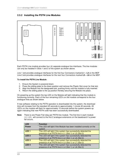
2.5.2 Installing the PSTN Line Modules<br />
Advantage <strong>4800</strong><br />
4 ISDN Line Card<br />
Item Code:<br />
Power<br />
LED 1<br />
LED 2<br />
LED 3<br />
LED 4<br />
Applications<br />
Extensions<br />
2 2<br />
Extensions<br />
1<br />
ADSL<br />
Lines 2<br />
Lines 1<br />
6 5 4 3 2 1<br />
L5<br />
L6<br />
L7<br />
L8<br />
L1<br />
L2<br />
L3<br />
L4<br />
Each PSTN Line module provides four (4) separate analogue line interfaces. The line modules<br />
can only be installed in Slots 1 and 2 of the system as shown above.<br />
Line 1 slot provides analogue interfaces for the first four Connectors marked L1 – L4 on the MDF<br />
Line 2 slot provides analogue interfaces for the next four Connectors marked L5 – L8 on the MDF<br />
To install the PSTN Line Module:<br />
1. Ensure the System is powered down.<br />
2. Press the sliding plate to the down position and remove the Plastic Slot cover for that slot.<br />
3. Align the Module into the designated slot, pushing firmly until the module is fully inserted.<br />
4. Return the sliding plate to the up position thereby securing the Module into place.<br />
On powering up the system the top LED on the Module will light indicating that the module is<br />
functioning correctly. Each of the four remaining LED’s on the module correspond to the four<br />
analogue lines as shown below.<br />
If new software relating to the PSTN operation is downloaded into the system, the download<br />
time will increase from the standard 45 seconds to approximately 1 minute 40 seconds. All<br />
LED’s on the module will flash for approximately 15 seconds before the system powers-up<br />
again indicating that new PSTN code has been successfully downloaded.<br />
Note: There is one Power Fail relay per PSTN line module. The first line in each module<br />
( L1, L5 ) will connect to the first 2 analogue extensions on the baseboard if a power<br />
fail occurs.<br />
LED<br />
Power<br />
LED 1<br />
LED 2<br />
LED 3<br />
LED 4<br />
Function<br />
This LED will light if the Module has been installed correctly on the<br />
system<br />
This LED will light if the system has successfully detected the<br />
presence of an PSTN line in L1 (Slot 1) or L5 (Slot 2)<br />
This LED will light if the system has successfully detected the<br />
presence of an PSTN line in L2 (Slot 1) or L6 (Slot 2)<br />
This LED will light if the system has successfully detected the<br />
presence of an PSTN line in L3 (Slot 1) or L7 (Slot 2)<br />
This LED will light if the system has successfully detected the<br />
presence of an PSTN line in L4 (Slot 1) or L8 (Slot 2)<br />
13