- Page 1 and 2:
©
- Page 3 and 4:
DID's Quality Assurance ¡Customer
- Page 5 and 6:
Cautions Cautions for handling of c
- Page 7 and 8:
Cautions Cautions for using roller
- Page 9 and 10:
INDEX 1 Roller Chains for Power Tra
- Page 11 and 12:
Index (In alphabetical order) Produ
- Page 13 and 14:
12
- Page 15 and 16:
Roller Chains for Power Transmissio
- Page 17 and 18:
Roller Chains for Power Transmissio
- Page 19 and 20:
Roller Chains for Power Transmissio
- Page 21 and 22:
Roller Chains for Power Transmissio
- Page 23 and 24:
Roller Chains for Power Transmissio
- Page 25 and 26:
Roller Chains for Power Transmissio
- Page 27 and 28:
Roller Chains for Power Transmissio
- Page 29 and 30:
Roller Chains for Power Transmissio
- Page 31 and 32:
Roller Chains for Power Transmissio
- Page 33 and 34:
Roller Chains for Power Transmissio
- Page 35 and 36:
Roller Chains for Power Transmissio
- Page 37 and 38:
Roller Chains for Power Transmissio
- Page 39 and 40:
Roller Chains for Power Transmissio
- Page 41 and 42:
Roller Chains for Power Transmissio
- Page 43 and 44:
Roller Chains for Power Transmissio
- Page 45 and 46:
Roller Chains for Power Transmissio
- Page 47 and 48:
Roller Chains for Power Transmissio
- Page 49 and 50:
Roller Chains for Power Transmissio
- Page 51 and 52:
Roller Chains for Power Transmissio
- Page 53 and 54:
Roller Chains for Power Transmissio
- Page 55 and 56:
Roller Chains for Power Transmissio
- Page 57 and 58:
Roller Chains for Power Transmissio
- Page 59 and 60:
Roller Chains for Power Transmissio
- Page 61 and 62:
Roller Chains for Power Transmissio
- Page 63 and 64:
Roller Chains for Power Transmissio
- Page 65 and 66:
Roller Chains for Power Transmissio
- Page 67 and 68:
Roller Chains for Power Transmissio
- Page 69 and 70:
Roller Chains for Power Transmissio
- Page 71 and 72:
Roller Chains for Power Transmissio
- Page 73 and 74:
Roller Chains for Power Transmissio
- Page 75 and 76:
Roller Chains for Power Transmissio
- Page 77 and 78:
Roller Chains for Power Transmissio
- Page 79 and 80:
Roller Chains for Power Transmissio
- Page 81 and 82:
Roller Chains for Power Transmissio
- Page 83 and 84:
Roller Chains for Power Transmissio
- Page 85 and 86:
Roller Chains for Power Transmissio
- Page 87 and 88:
Roller Chains for Power Transmissio
- Page 89 and 90:
Roller Chains for Power Transmissio
- Page 91 and 92:
Roller Chains for Power Transmissio
- Page 93 and 94:
Roller Chains for Power Transmissio
- Page 95 and 96:
Roller Chains for Power Transmissio
- Page 97 and 98:
Roller Chains for Power Transmissio
- Page 99 and 100:
Roller Chains for Power Transmissio
- Page 101 and 102:
Roller Chains for Power Transmissio
- Page 103 and 104:
Roller Chains for Power Transmissio
- Page 105 and 106:
Roller Chains for Power Transmissio
- Page 107 and 108:
Roller Chains for Power Transmissio
- Page 109 and 110:
Roller Chains for Power Transmissio
- Page 111 and 112:
Roller Chains for Power Transmissio
- Page 113 and 114:
Roller Chains for Power Transmissio
- Page 115 and 116:
Roller Chains for Power Transmissio
- Page 117 and 118:
Roller Chains for Power Transmissio
- Page 119 and 120:
Roller Chains for Power Transmissio
- Page 121 and 122:
Roller Chains for Power Transmissio
- Page 123 and 124:
Roller Chains for Power Transmissio
- Page 125 and 126:
Roller Chains for Power Transmissio
- Page 127 and 128:
Roller Chains for Power Transmissio
- Page 129 and 130:
Roller Chains for Power Transmissio
- Page 131 and 132:
Roller Chains for Power Transmissio
- Page 133 and 134:
Roller Chains for Power Transmissio
- Page 135 and 136:
Roller Chains for Power Transmissio
- Page 137 and 138:
Roller Chains for Power Transmissio
- Page 140 and 141:
Small Conveyor Chains ¡General ¡S
- Page 142 and 143:
Classification Major division Mediu
- Page 144 and 145:
Hi-Guard (E) Double Guard (WG) Envi
- Page 146 and 147:
Standard Attachment Chart : In sto
- Page 148 and 149:
Tensile strength index 100 Temperat
- Page 150 and 151:
Dirty Environment Tensile strength
- Page 152 and 153:
Dirty Environment Dusty Tensile str
- Page 154 and 155:
Dirty Environment Dusty Maintenance
- Page 156 and 157:
Tensile Temperature strength index
- Page 158 and 159:
Corrosive Atmosphere Moisture, Salt
- Page 160 and 161:
Corrosive Atmosphere Moisture, Salt
- Page 162 and 163:
Corrosive Atmosphere Moisture, Salt
- Page 164 and 165:
Corrosive Atmosphere Moisture, Salt
- Page 166 and 167:
Corrosive Atmosphere Clean Areas Mo
- Page 168 and 169:
Corrosive Atmosphere Alkaline Envir
- Page 170 and 171:
Double Guard Chain (WG) qApprox. tw
- Page 172 and 173:
Large roller (R) and small rollers
- Page 174 and 175:
Dimensions of Sprocket for Double P
- Page 176 and 177:
Standard Roller Chain Attachment :
- Page 178 and 179:
Dimensions of Standard Roller Chain
- Page 180 and 181:
Dirty Environment Tensile strength
- Page 182 and 183:
Dirty Environment Dusty Tensile str
- Page 184 and 185:
Dirty Environment Dusty Maintenance
- Page 186 and 187:
Tensile Temperature strength index
- Page 188 and 189:
Corrosive Atmosphere Moisture, Salt
- Page 190 and 191:
Corrosive Atmosphere Moisture, Salt
- Page 192 and 193:
Corrosive Atmosphere Moisture, Salt
- Page 194 and 195:
Corrosive Atmosphere Moisture, Salt
- Page 196 and 197:
Corrosive Atmosphere Clean Areas Mo
- Page 198 and 199:
Flexible Chain (FX) Other Conveyor
- Page 200 and 201:
¡Duplex Every-two-link Top Roller
- Page 202 and 203:
Dimensions of chain body Chain No.
- Page 204 and 205:
[Type indication] Guide links are a
- Page 206 and 207:
Meandering prevention chains An R r
- Page 208 and 209:
Side Roller Chain with Breaks (TRB)
- Page 210 and 211:
Small Conveyor Chains Flexible Chai
- Page 212 and 213:
211
- Page 214 and 215:
Calculation formulas of theoretical
- Page 216 and 217:
Strength of Loaded Components The l
- Page 218 and 219:
Conveyor Chains ¡Outline of Conve
- Page 220 and 221:
Construction and Components of DK C
- Page 222 and 223:
DK Conveyor Chains Standard Conveyo
- Page 224 and 225:
Classified by Material and Heat Tre
- Page 226 and 227:
Chain Specifications 1. Standard Co
- Page 228 and 229:
Dimensional Drawings: DK 07075, DK
- Page 230 and 231:
Dimensional Drawings: DK 11100, DK
- Page 232 and 233:
Dimensional Drawings: DK 19200, DK
- Page 234 and 235:
Dimensional Drawings: DK 32200, DK
- Page 236 and 237:
Dimensional Drawings: DK 65300 and
- Page 238 and 239:
Dimensional Drawings: DK 08066 and
- Page 240 and 241:
Dimensional Drawings: DK 11152 (for
- Page 242 and 243:
Dimensional Drawings: DK 19152 (for
- Page 244 and 245:
DK Conveyor Chains Anti-seizing Rol
- Page 246 and 247:
Dimensional Drawings: DK 07075, DK
- Page 248 and 249:
Dimensional Drawings: DK 11100, DK
- Page 250 and 251:
Dimensional Drawings: DK 19200, DK
- Page 252 and 253:
Dimensional Drawings: DK 32200, DK
- Page 254 and 255:
Dimensional Drawings: DK 65300 and
- Page 256 and 257:
Dimensional Drawings: DK 08101 (for
- Page 258 and 259:
Dimensional Drawings: DK 11152 (for
- Page 260 and 261:
Dimensional Drawings: DK 19152 (for
- Page 262 and 263:
DK Conveyor Chains Bearing Assemble
- Page 264 and 265:
Dimensional Drawings: DK 13150 and
- Page 266 and 267:
Dimensional Drawings: DK 25200, DK
- Page 268 and 269:
Dimensional Drawings: DK 50250, DK
- Page 270 and 271:
Dimensional Drawings: DK 19152 (for
- Page 272 and 273:
DK Conveyor Chains Seal Chain Seal
- Page 274 and 275:
DK Conveyor Chains Strong H-type an
- Page 276 and 277:
Dimensional Drawings: Strong Z-type
- Page 278 and 279:
DK Conveyor Chains High Link-Plate
- Page 280 and 281:
DK Conveyor Chains Conveyor Chain w
- Page 282 and 283:
(a) Continuous Flow Conveyor Chain
- Page 284 and 285:
(b) Chains for Dust Conveyor This c
- Page 286 and 287:
Eco Slight (small sized apron conve
- Page 288 and 289:
Bucket Elevator Chains A bucket ele
- Page 290 and 291:
Flat Top Type Chain for Coil Convey
- Page 292 and 293: Block Chain When a chain having a h
- Page 294 and 295: DK Specialty Conveyor Chains Water
- Page 296 and 297: Sewage Treatment Chain (WS or WAS T
- Page 298 and 299: Heat treated stainless steel provid
- Page 300 and 301: DK Specialty Conveyor Chains 3D Ben
- Page 302 and 303: FH Type Chain for Freeyor An FH Typ
- Page 304 and 305: Booster Chain for Rivetless Chain A
- Page 306 and 307: Chain Bearing Roller PAT. Chain Bea
- Page 308 and 309: Deposit prevention type / IWD Dime
- Page 310 and 311: Long pan conveyor Apron conveyor A
- Page 312 and 313: Conveyors for slung articles Power-
- Page 314 and 315: Photo / Sprocket Photos of Specialt
- Page 316 and 317: 315 Photo/ Sprocket Sprocket Tooth
- Page 318 and 319: Tooth Width of Conveyor Chain Sproc
- Page 320 and 321: Outer Diameter of DK Conveyor Chain
- Page 322 and 323: Outer Diameter of DK Conveyor Chain
- Page 324 and 325: Outer Diameter of DK Conveyor Chain
- Page 326 and 327: Conveyor Chain Sprocket for NSE-typ
- Page 328 and 329: Shaft diameter and hub dimensions S
- Page 330 and 331: 329
- Page 332 and 333: For Use at High-temperature Chains
- Page 334 and 335: Calculation Formula for Horizontal,
- Page 336 and 337: Examples of Calculation for Selecti
- Page 338 and 339: Technical Data Allowable Loads of R
- Page 340 and 341: Technical Data Corrosion Resistance
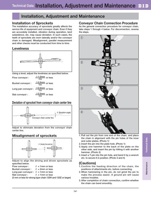
- Page 344 and 345: Lubrication To extend the life of c
- Page 346 and 347: Glossary Terms such as average tens