DID 60 standard roller chain - Big Bike Webshop
DID 60 standard roller chain - Big Bike Webshop
DID 60 standard roller chain - Big Bike Webshop

You also want an ePaper? Increase the reach of your titles
YUMPU automatically turns print PDFs into web optimized ePapers that Google loves.
Allowable<br />
Load<br />
130<br />
Tensile<br />
strength index<br />
110<br />
Temperature<br />
Range in Use<br />
10<br />
80<br />
AGRICULTURE<br />
CONST-<br />
RUCTION<br />
OUTDOOR<br />
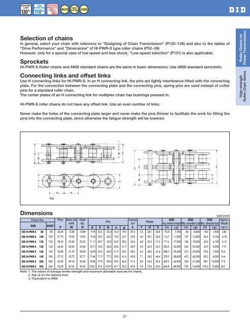
Selection of <strong>chain</strong>s<br />
In general, select your <strong>chain</strong> with reference to "Designing of Chain Transmission" (P120~126) and also to the tables of<br />
"Drive Performance" and "Dimensions" of HI-PWR-S type <strong>roller</strong> <strong>chain</strong>s (P52~59)<br />
However, only for a special case of low speed and less shock, "Low-speed selection" (P121) is also applicable.<br />
Sprockets<br />
HI-PWR-S Roller <strong>chain</strong>s and ANSI <strong>standard</strong> <strong>chain</strong>s are the same in basic dimensions. Use ANSI <strong>standard</strong> sprockets.<br />
Connecting links and offset links<br />
Use H connecting links for HI-PWR-S. In an H connecting link, the pins are lightly interference-fitted with the connecting<br />
plate. For the connection between the connecting plate and the connecting pins, spring pins are used instead of cotter<br />
pins for a <strong>standard</strong> <strong>roller</strong> <strong>chain</strong>.<br />
The center plates of an H connecting link for multiplex <strong>chain</strong> has bushings pressed in.<br />
HI-PWR-S <strong>roller</strong> <strong>chain</strong>s do not have any offset link. Use an even number of links.<br />
Roller Chains for<br />
Power Transmission<br />
High-strength<br />
Roller Chain Series<br />
Never make the holes of the connecting plate larger and never make the pins thinner to facilitate the work for fitting the<br />
pins into the connecting plate, since otherwise the fatigue strength will be lowered.<br />
HJ<br />
Dimensions<br />
Chain No.<br />
<strong>DID</strong><br />
<strong>DID</strong> HI-PWR-S 80<br />
<strong>DID</strong> HI-PWR-S 100<br />
<strong>DID</strong> HI-PWR-S 120<br />
<strong>DID</strong> HI-PWR-S 140<br />
<strong>DID</strong> HI-PWR-S 1<strong>60</strong><br />
<strong>DID</strong> HI-PWR-S 180<br />
<strong>DID</strong> HI-PWR-S 200<br />
<strong>DID</strong> HI-PWR-S 240<br />
ANSI*<br />
080<br />
100<br />
120<br />
140<br />
1<strong>60</strong><br />
180<br />
200<br />
240<br />
Pitch Roller link Roller<br />
Transverse<br />
width dia.<br />
Pin<br />
pitch<br />
Plate<br />
P W D d E G e g C T H h<br />
25.40<br />
31.75<br />
38.10<br />
44.45<br />
50.80<br />
57.15<br />
63.50<br />
76.20<br />
15.88<br />
19.05<br />
25.40<br />
25.40<br />
31.75<br />
35.72<br />
38.10<br />
47.63<br />
15.88<br />
19.05<br />
22.23<br />
25.40<br />
28.58<br />
35.71<br />
39.68<br />
47.63<br />
7.94<br />
9.54<br />
11.11<br />
12.71<br />
14.29<br />
17.46<br />
19.85<br />
23.81<br />
32.6<br />
39.5<br />
49.7<br />
53.6<br />
63.6<br />
71.5<br />
77.9<br />
95.2<br />
35.4<br />
42.5<br />
53.0<br />
58.4<br />
68.2<br />
77.3<br />
85.0<br />
102.9<br />
16.4<br />
19.8<br />
24.9<br />
26.8<br />
31.9<br />
35.8<br />
39.0<br />
47.7<br />
19.0<br />
22.7<br />
28.2<br />
31.7<br />
36.5<br />
41.6<br />
46.0<br />
55.3<br />
29.3<br />
35.8<br />
45.4<br />
48.9<br />
58.5<br />
65.8<br />
71.6<br />
87.8<br />
3.2<br />
4.0<br />
4.8<br />
5.6<br />
6.4<br />
7.1<br />
8.0<br />
9.5<br />
24.1<br />
30.1<br />
36.2<br />
42.2<br />
48.2<br />
54.2<br />
<strong>60</strong>.2<br />
72.2<br />
20.8<br />
26.0<br />
31.2<br />
36.3<br />
41.4<br />
46.6<br />
52.0<br />
62.0<br />
Note: 1. The values of average tensile strength and maximum allowable load are for <strong>chain</strong>s.<br />
2. Ask us for the delivery time.<br />
3. *Equivalent to ANSI<br />
Unit (mm)<br />
<strong>DID</strong> <strong>DID</strong> <strong>DID</strong> Approx.<br />
Avg. tensile strength Max. allowable load Max. allowable load Weight<br />
<br />
075.51 7,700 84 8,<strong>60</strong>0 18.6 1,900 02.82<br />
116.70 11,900 127 13,000 30.4 3,100 04.18<br />
171.<strong>60</strong> 17,500 186 19,000 40.2 4,100 06.12<br />
225.50 23,000 245 25,000 53.9 5,500 07.71<br />
288.30 29,400 313 32,000 70.6 7,200 10.50<br />
378.50 38,<strong>60</strong>0 412 42,000 83.3 8,500 14.40<br />
459.90 46,900 500 51,000 98.1 10,000 17.50<br />
666.80 68,000 725 74,000 132.4 13,500 24.70<br />
51