1735 Technical Manual - Novatech Controls
1735 Technical Manual - Novatech Controls
1735 Technical Manual - Novatech Controls

Create successful ePaper yourself
Turn your PDF publications into a flip-book with our unique Google optimized e-Paper software.
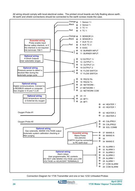
All wiring should comply with local electrical codes. The printed circuit boards are fully floating above earth.<br />
All earth and shield connections should be connected to the earth screws inside the case.<br />
Orange<br />
Black<br />
Red<br />
1 Sensor 1+<br />
2 Sensor 1-<br />
3 TC 1+<br />
4 TC 1-<br />
Essential wiring<br />
Probe enable input<br />
Burner safety interlock, or if<br />
the interlock is not required<br />
link terminals 10&11<br />
Optional wiring<br />
4-20mA Outputs<br />
User selectable ranges<br />
Optional wiring<br />
Pressure sensor to detect a<br />
blocked filter during the<br />
automatic purge cycle<br />
Optional wiring<br />
Digital communications. Connect to<br />
a MODBUS network or computer.<br />
See chapter 4.15 and 7.2.25<br />
Orange<br />
Black<br />
Red<br />
5 SENSOR 2+<br />
6 SENSOR 2-<br />
7 AUX TC 2+<br />
8 AUX TC 2-<br />
9 5VDC<br />
10 BURNER INPUT<br />
11 BURNER INPUT<br />
12 OUTPUT 1+<br />
13 OUTPUT 1-<br />
14 OUTPUT 2+<br />
15 OUTPUT 2-<br />
16 FLOW SWITCH<br />
17 FLOW SWITCH<br />
18 RS232 Rx<br />
19 RS232 Tx<br />
20 NETWORK -<br />
21 NETWORK +<br />
22 NETWORK COM<br />
Optional wiring<br />
RGS temperature sensor<br />
or External dry oxygen<br />
23 +V<br />
24 BFT+<br />
25 BFT-<br />
44 HEATER 1<br />
43 HEATER 1<br />
Oxygen Probe #1<br />
42 HEATER 2<br />
41 HEATER 2<br />
Oxygen Probe #2<br />
Optional wiring<br />
Gas solenoids, MAINS VOLTAGE output<br />
Automatic system calibration checking or<br />
filter purging<br />
Essential wiring<br />
Mains Power<br />
100-240VAC<br />
EARTH must be connected<br />
to PE earth-stud<br />
40 CAL/PRG1<br />
39 CAL/PRG2<br />
38 SOL COMM<br />
37 MAINS A<br />
36 MAINS N<br />
35<br />
34 MAINS E<br />
Optional wiring<br />
Alarm relays<br />
User programmable, NC contacts<br />
DO NOT USE MAINS VOLTAGE and LOW<br />
VOLTAGE on ADJACENT TERMINALS<br />
33 ALARM 3<br />
32 ALARM 3<br />
31 ALARM 2<br />
30 ALARM 2<br />
29 ALARM 1<br />
28 ALARM 1<br />
27 COM ALARM<br />
26 COM ALARM<br />
Connection Diagram for <strong>1735</strong> Transmitter and one or two 1232 Unheated Probes<br />
April 2012<br />
24 <strong>1735</strong> Water Vapour Transmitter