1735 Technical Manual - Novatech Controls
1735 Technical Manual - Novatech Controls
1735 Technical Manual - Novatech Controls

Create successful ePaper yourself
Turn your PDF publications into a flip-book with our unique Google optimized e-Paper software.
4.23 Dust in the Flue Gas<br />
For heated probes the preferred method of mounting for dust-laden applications is facing vertically<br />
downwards with the filter removed. Probes can also be mounted horizontally with no filter with some dusts.<br />
An occasional automatic back purge is helpful in this case.<br />
Normally heated probes are supplied with filters for applications with particulates in the process gas. The<br />
probe response time should be tested when the probe is first installed, and then regularly until it remains<br />
constant for a significant period. Filter purging should be set up on the time periods determined by these<br />
tests. To test the probe response time, use a stopwatch to obtain the time for a probe to achieve a 63 %<br />
change from one reading to another. If a probe filter blocks completely in a short period of time, then there is<br />
no option but to use the probe without the filter. A trial probe with filter can be installed to test whether a filter<br />
blockage is likely to occur.<br />
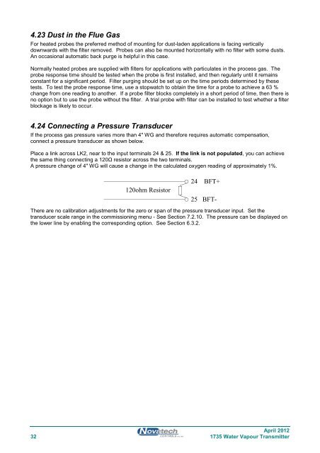
4.24 Connecting a Pressure Transducer<br />
If the process gas pressure varies more than 4" WG and therefore requires automatic compensation,<br />
connect a pressure transducer as shown below.<br />
Place a link across LK2, near to the input terminals 24 & 25. If the link is not populated, you can achieve<br />
the same thing connecting a 120Ω resistor across the two terminals.<br />
A pressure change of 4" WG will cause a change in the calculated oxygen reading of approximately 1%.<br />
120ohm Resistor<br />
24 BFT+<br />
25 BFT-<br />
There are no calibration adjustments for the zero or span of the pressure transducer input. Set the<br />
transducer scale range in the commissioning menu - See Section 7.2.10. The pressure can be displayed on<br />
the lower line by enabling the corresponding option. See Section 6.3.2.<br />
April 2012<br />
32 <strong>1735</strong> Water Vapour Transmitter