- Page 1 and 2:
ISOCAM Interactive Analysis User’
- Page 3:
Michael Rupen (NRAO) Jaqui Sam Lone
- Page 6 and 7:
vi CONTENTS 8 Polarization observat
- Page 8 and 9:
viii CONTENTS 14.4.6 x3d as a calib
- Page 10 and 11:
x CONTENTS 19.3 A beam-switch obser
- Page 12 and 13:
xii CONTENTS B CIA command short-li
- Page 14 and 15:
xiv CONTENTS
- Page 16 and 17:
xvi LIST OF FIGURES 14.13The raster
- Page 18 and 19:
xviii LIST OF FIGURES
- Page 20 and 21:
xx LIST OF TABLES
- Page 22 and 23:
2 CHAPTER 1. ABOUT THE CIA USER’S
- Page 24 and 25:
4 CHAPTER 2. ABOUT CIA 2.2 System r
- Page 26 and 27:
6 CHAPTER 2. ABOUT CIA Figure 2.2:
- Page 28 and 29:
8 CHAPTER 2. ABOUT CIA In addition,
- Page 30 and 31:
10 CHAPTER 2. ABOUT CIA 2.3.4 Custo
- Page 32 and 33:
12 CHAPTER 2. ABOUT CIA LOG Log fil
- Page 34 and 35:
14 CHAPTER 2. ABOUT CIA This will p
- Page 36 and 37:
16 CHAPTER 2. ABOUT CIA % device, p
- Page 38 and 39:
18 CHAPTER 2. ABOUT CIA
- Page 41:
Introduction The Quick Start Guide
- Page 44 and 45:
24 CHAPTER 3. RASTER OBSERVATION (C
- Page 46 and 47:
26 CHAPTER 3. RASTER OBSERVATION (C
- Page 48 and 49:
28 CHAPTER 3. RASTER OBSERVATION (C
- Page 50 and 51:
30 CHAPTER 3. RASTER OBSERVATION (C
- Page 52 and 53:
32 CHAPTER 4. STARING OBSERVATION (
- Page 54 and 55:
34 CHAPTER 4. STARING OBSERVATION (
- Page 56 and 57:
36 CHAPTER 5. SOLAR SYSTEM OBJECT O
- Page 58 and 59:
38 CHAPTER 5. SOLAR SYSTEM OBJECT O
- Page 60 and 61:
40 CHAPTER 5. SOLAR SYSTEM OBJECT O
- Page 62 and 63:
42 CHAPTER 6. BEAM-SWITCH OBSERVATI
- Page 64 and 65:
44 CHAPTER 6. BEAM-SWITCH OBSERVATI
- Page 66 and 67:
46 CHAPTER 6. BEAM-SWITCH OBSERVATI
- Page 68 and 69:
48 CHAPTER 7. CVF OBSERVATION (CAM0
- Page 70 and 71:
50 CHAPTER 7. CVF OBSERVATION (CAM0
- Page 72 and 73:
52 CHAPTER 8. POLARIZATION OBSERVAT
- Page 74 and 75:
54 CHAPTER 8. POLARIZATION OBSERVAT
- Page 76 and 77:
56 CHAPTER 8. POLARIZATION OBSERVAT
- Page 79:
Introduction The purpose of Part II
- Page 82 and 83:
62 CHAPTER 9. THE DATA PRODUCTS AND
- Page 84 and 85:
64 CHAPTER 9. THE DATA PRODUCTS AND
- Page 86 and 87:
66 CHAPTER 9. THE DATA PRODUCTS AND
- Page 88 and 89:
68 CHAPTER 10. FIRST LOOK AT THE DA
- Page 90 and 91:
70 CHAPTER 10. FIRST LOOK AT THE DA
- Page 92 and 93:
72 CHAPTER 10. FIRST LOOK AT THE DA
- Page 94 and 95:
74 CHAPTER 11. INTRODUCTION TO CIA
- Page 96 and 97:
76 CHAPTER 11. INTRODUCTION TO CIA
- Page 98 and 99:
78 CHAPTER 12. DATA SLICING 3. At t
- Page 100 and 101:
80 CHAPTER 12. DATA SLICING CIA> ns
- Page 102 and 103:
82 CHAPTER 12. DATA SLICING equal t
- Page 104 and 105:
84 CHAPTER 12. DATA SLICING OR CIA>
- Page 106 and 107:
86 CHAPTER 12. DATA SLICING 70 16.0
- Page 108 and 109:
88 CHAPTER 12. DATA SLICING • Sel
- Page 110 and 111:
90 CHAPTER 12. DATA SLICING We sugg
- Page 112 and 113:
92 CHAPTER 12. DATA SLICING title d
- Page 114 and 115:
94 CHAPTER 12. DATA SLICING • Sel
- Page 116 and 117:
96 CHAPTER 13. DATA CALIBRATION 13.
- Page 118 and 119:
98 CHAPTER 13. DATA CALIBRATION •
- Page 120 and 121:
100 CHAPTER 13. DATA CALIBRATION 13
- Page 122 and 123:
102 CHAPTER 13. DATA CALIBRATION 13
- Page 124 and 125:
104 CHAPTER 13. DATA CALIBRATION Fi
- Page 126 and 127:
106 CHAPTER 13. DATA CALIBRATION au
- Page 128 and 129:
108 CHAPTER 13. DATA CALIBRATION 2.
- Page 130 and 131:
110 CHAPTER 13. DATA CALIBRATION 13
- Page 132 and 133:
112 CHAPTER 13. DATA CALIBRATION 13
- Page 134 and 135:
114 CHAPTER 14. IMAGE ANALYSIS AND
- Page 136 and 137:
116 CHAPTER 14. IMAGE ANALYSIS AND
- Page 138 and 139:
118 CHAPTER 14. IMAGE ANALYSIS AND
- Page 140 and 141:
120 CHAPTER 14. IMAGE ANALYSIS AND
- Page 142 and 143:
122 CHAPTER 14. IMAGE ANALYSIS AND
- Page 144 and 145:
124 CHAPTER 14. IMAGE ANALYSIS AND
- Page 146 and 147:
126 CHAPTER 14. IMAGE ANALYSIS AND
- Page 148 and 149:
128 CHAPTER 14. IMAGE ANALYSIS AND
- Page 150 and 151:
130 CHAPTER 14. IMAGE ANALYSIS AND
- Page 152 and 153:
132 CHAPTER 14. IMAGE ANALYSIS AND
- Page 154 and 155:
134 CHAPTER 14. IMAGE ANALYSIS AND
- Page 156 and 157:
136 CHAPTER 14. IMAGE ANALYSIS AND
- Page 158 and 159:
138 CHAPTER 14. IMAGE ANALYSIS AND
- Page 160 and 161:
140 CHAPTER 14. IMAGE ANALYSIS AND
- Page 162 and 163:
142 CHAPTER 14. IMAGE ANALYSIS AND
- Page 164 and 165:
144 CHAPTER 14. IMAGE ANALYSIS AND
- Page 166 and 167:
146 CHAPTER 14. IMAGE ANALYSIS AND
- Page 168 and 169:
148 CHAPTER 14. IMAGE ANALYSIS AND
- Page 170 and 171:
150 CHAPTER 14. IMAGE ANALYSIS AND
- Page 172 and 173:
152 CHAPTER 14. IMAGE ANALYSIS AND
- Page 174 and 175:
154 CHAPTER 14. IMAGE ANALYSIS AND
- Page 176 and 177:
156 CHAPTER 14. IMAGE ANALYSIS AND
- Page 179 and 180:
Introduction The purpose of this pa
- Page 181 and 182:
Chapter 15 CIA data structure high-
- Page 183 and 184:
15.2. OBSERVATION DATA STRUCTURES 1
- Page 185 and 186:
15.2. OBSERVATION DATA STRUCTURES 1
- Page 187 and 188:
15.2. OBSERVATION DATA STRUCTURES 1
- Page 189 and 190:
15.2. OBSERVATION DATA STRUCTURES 1
- Page 191 and 192:
15.3. CALIBRATION DATA STRUCTURE (C
- Page 193 and 194:
15.3. CALIBRATION DATA STRUCTURE (C
- Page 195 and 196:
15.3. CALIBRATION DATA STRUCTURE (C
- Page 197 and 198:
15.4. AUXILIARY CALIBRATION DATA 17
- Page 199 and 200:
15.4. AUXILIARY CALIBRATION DATA 17
- Page 201 and 202:
15.5. PREPARED DATA STRUCTURE (PDS)
- Page 203 and 204:
15.5. PREPARED DATA STRUCTURE (PDS)
- Page 205 and 206:
15.5. PREPARED DATA STRUCTURE (PDS)
- Page 207 and 208:
Chapter 16 Data structure manipulat
- Page 209 and 210:
16.1. CIA DATA STRUCTURE INTERFACE
- Page 211 and 212:
16.1. CIA DATA STRUCTURE INTERFACE
- Page 213 and 214:
16.2. AN EXAMPLE OF SAD MANIPULATIO
- Page 215 and 216:
16.4. MANIPULATING THE MASK 195 and
- Page 217 and 218:
16.5. CDS DATA EXTRACTION 197 16.5
- Page 219 and 220:
16.6. MANIPULATING CIA DATA STRUCTU
- Page 221 and 222:
Chapter 17 Importing ISO data produ
- Page 223 and 224:
17.2. IMPORTING FITS TO REGULAR IDL
- Page 225 and 226:
Chapter 18 Export of CIA data struc
- Page 227 and 228:
18.3. EXPORT FOR ARCHIVING 207 CIA>
- Page 229:
Part IV Advanced Use of CIA 209
- Page 232 and 233:
212
- Page 234 and 235:
214 CHAPTER 19. ADVANCED SLICING 19
- Page 236 and 237:
216 CHAPTER 19. ADVANCED SLICING Fi
- Page 238 and 239:
218 CHAPTER 19. ADVANCED SLICING 19
- Page 240 and 241:
220 CHAPTER 19. ADVANCED SLICING 19
- Page 242 and 243:
222 CHAPTER 19. ADVANCED SLICING 19
- Page 244 and 245:
224 CHAPTER 19. ADVANCED SLICING 19
- Page 246 and 247:
226 CHAPTER 19. ADVANCED SLICING va
- Page 248 and 249:
228 CHAPTER 19. ADVANCED SLICING Fo
- Page 250 and 251:
230 CHAPTER 19. ADVANCED SLICING
- Page 252 and 253:
232 CHAPTER 20. ADVANCED DATA CALIB
- Page 254 and 255:
234 CHAPTER 20. ADVANCED DATA CALIB
- Page 256 and 257:
236 CHAPTER 20. ADVANCED DATA CALIB
- Page 258 and 259:
238 CHAPTER 20. ADVANCED DATA CALIB
- Page 260 and 261:
240 CHAPTER 20. ADVANCED DATA CALIB
- Page 262 and 263: 242 CHAPTER 20. ADVANCED DATA CALIB
- Page 264 and 265: 244 CHAPTER 20. ADVANCED DATA CALIB
- Page 266 and 267: 246 CHAPTER 20. ADVANCED DATA CALIB
- Page 268 and 269: 248 CHAPTER 20. ADVANCED DATA CALIB
- Page 270 and 271: 250 CHAPTER 20. ADVANCED DATA CALIB
- Page 272 and 273: 252 CHAPTER 20. ADVANCED DATA CALIB
- Page 274 and 275: 254 CHAPTER 20. ADVANCED DATA CALIB
- Page 276 and 277: 256 CHAPTER 20. ADVANCED DATA CALIB
- Page 278 and 279: 258 CHAPTER 20. ADVANCED DATA CALIB
- Page 280 and 281: 260 CHAPTER 20. ADVANCED DATA CALIB
- Page 282 and 283: 262 CHAPTER 20. ADVANCED DATA CALIB
- Page 284 and 285: 264 CHAPTER 20. ADVANCED DATA CALIB
- Page 286 and 287: 266 CHAPTER 20. ADVANCED DATA CALIB
- Page 288 and 289: 268 CHAPTER 20. ADVANCED DATA CALIB
- Page 290 and 291: 270 CHAPTER 20. ADVANCED DATA CALIB
- Page 292 and 293: 272 CHAPTER 20. ADVANCED DATA CALIB
- Page 294 and 295: 274 CHAPTER 21. USING SLICE WITHIN
- Page 296 and 297: 276 CHAPTER 21. USING SLICE WITHIN
- Page 298 and 299: 278 CHAPTER 21. USING SLICE WITHIN
- Page 300 and 301: 280 CHAPTER 21. USING SLICE WITHIN
- Page 302 and 303: 282 CHAPTER 21. USING SLICE WITHIN
- Page 304 and 305: 284 CHAPTER 21. USING SLICE WITHIN
- Page 306 and 307: 286 CHAPTER 21. USING SLICE WITHIN
- Page 308 and 309: 288 CHAPTER 21. USING SLICE WITHIN
- Page 310 and 311: 290 CHAPTER 21. USING SLICE WITHIN
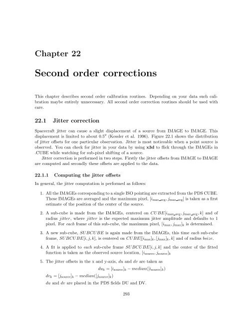
- Page 314 and 315: 294 CHAPTER 22. SECOND ORDER CORREC
- Page 316 and 317: 296 CHAPTER 22. SECOND ORDER CORREC
- Page 318 and 319: 298 CHAPTER 23. X CIA REFERENCE GUI
- Page 320 and 321: 300 CHAPTER 23. X CIA REFERENCE GUI
- Page 322 and 323: 302 CHAPTER 23. X CIA REFERENCE GUI
- Page 324 and 325: 304 CHAPTER 23. X CIA REFERENCE GUI
- Page 326 and 327: 306 APPENDIX A. GLOSSARY beam-switc
- Page 328 and 329: 308 APPENDIX A. GLOSSARY FITS (data
- Page 330 and 331: 310 APPENDIX A. GLOSSARY raster dat
- Page 332 and 333: 312 APPENDIX A. GLOSSARY
- Page 334 and 335: 314 APPENDIX B. CIA COMMAND SHORT-L
- Page 336 and 337: 316 APPENDIX B. CIA COMMAND SHORT-L
- Page 338 and 339: 318 APPENDIX B. CIA COMMAND SHORT-L
- Page 340 and 341: 320 APPENDIX C. THE ISO CD-ROM C.2.
- Page 342 and 343: 322 APPENDIX C. THE ISO CD-ROM Vari
- Page 344 and 345: 324 APPENDIX D. GUIDELINES FOR WRIT
- Page 346 and 347: 326 APPENDIX D. GUIDELINES FOR WRIT
- Page 348 and 349: 328 APPENDIX E. ISOCAM ASTROMETRY:
- Page 350 and 351: 330 APPENDIX E. ISOCAM ASTROMETRY:
- Page 352 and 353: 332 APPENDIX E. ISOCAM ASTROMETRY:
- Page 354 and 355: 334 APPENDIX E. ISOCAM ASTROMETRY:
- Page 356 and 357: 336 APPENDIX E. ISOCAM ASTROMETRY:
- Page 358 and 359: 338 APPENDIX F. WHAT IS NEW IN CIA
- Page 360 and 361: 340 APPENDIX F. WHAT IS NEW IN CIA
- Page 362 and 363:
342 APPENDIX F. WHAT IS NEW IN CIA
- Page 364 and 365:
344 APPENDIX G. WARNING MESSAGES IN
- Page 366 and 367:
346 APPENDIX H. PATCHED ASTROLIB AN
- Page 368 and 369:
348 APPENDIX I. UPGRADING OLD CIA S
- Page 370 and 371:
350 APPENDIX I. UPGRADING OLD CIA S
- Page 372 and 373:
352 APPENDIX J. REPORTING PROBLEMS
- Page 374 and 375:
354 APPENDIX K. TECHNICAL REPORTS S
- Page 376 and 377:
356 BIBLIOGRAPHY Okumura K., 1998,