Theta Controller User Manual
Theta Controller User Manual
Theta Controller User Manual

Create successful ePaper yourself
Turn your PDF publications into a flip-book with our unique Google optimized e-Paper software.
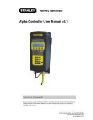
<strong>Theta</strong> <strong>Controller</strong><br />
Analyze Screens<br />
Options Screen<br />
Use the right arrow to move to the next tab or press the EXIT key, save the changes and return<br />
to the run screen. See Section 2.5.1.6.<br />
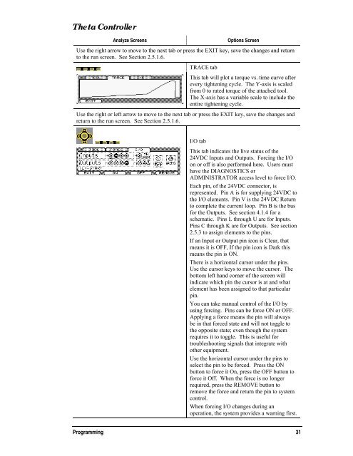
TRACE tab<br />
This tab will plot a torque vs. time curve after<br />
every tightening cycle. The Y-axis is scaled<br />
from 0 to rated torque of the attached tool.<br />
The X-axis has a variable scale to include the<br />
entire tightening cycle.<br />
Use the right or left arrow to move to the next tab or press the EXIT key, save the changes and<br />
return to the run screen. See Section 2.5.1.6.<br />
I/O tab<br />
This tab indicates the live status of the<br />
24VDC Inputs and Outputs. Forcing the I/O<br />
on or off is also performed here. <strong>User</strong>s must<br />
have the DIAGNOSTICS or<br />
ADMINISTRATOR access level to force I/O.<br />
Each pin, of the 24VDC connector, is<br />
represented. Pin A is for supplying 24VDC to<br />
the I/O elements. Pin V is the 24VDC Return<br />
to complete the current loop. Pin B is the bus<br />
for the Outputs. See section 4.1.4 for a<br />
schematic. Pins L through U are for Inputs.<br />
Pins C through K are for Outputs. See section<br />
2.5.3 to assign elements to the pins.<br />
If an Input or Output pin icon is Clear, that<br />
means it is OFF, If the pin icon is Dark this<br />
means the pin is ON.<br />
There is a horizontal cursor under the pins.<br />
Use the cursor keys to move the cursor. The<br />
bottom left hand corner of the screen will<br />
indicate which pin the cursor is at and what<br />
element has been assigned to that particular<br />
pin.<br />
You can take manual control of the I/O by<br />
using forcing. Pins can be force ON or OFF.<br />
Applying a force means the pin will always<br />
be in that forced state and will not toggle to<br />
the opposite state; even though the system<br />
requires it to toggle. This is useful for<br />
troubleshooting signals that integrate with<br />
other equipment.<br />
Use the horizontal cursor under the pins to<br />
select the pin to be forced. Press the ON<br />
button to force it On, press the OFF button to<br />
force it Off. When the force is no longer<br />
required, press the REMOVE button to<br />
remove the force and return the pin to system<br />
control.<br />
When forcing I/O changes during an<br />
operation, the system provides a warning first.<br />
Programming 31