Theta Controller User Manual
Theta Controller User Manual
Theta Controller User Manual

Create successful ePaper yourself
Turn your PDF publications into a flip-book with our unique Google optimized e-Paper software.
<strong>Theta</strong> <strong>Controller</strong><br />
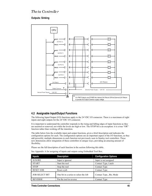
Outputs: Sinking<br />
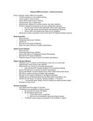
4.2 Assignable Input/Output Functions<br />
The following Input/Output (I/O) functions apply to the 24 VDC I/O connector. There is a maximum of eight<br />
inputs and eight outputs for the 24 VDC I/O connector.<br />
It is important to understand the controller responds to the rising and falling edges of input functions as they<br />
are asserted or removed, not while the levels are high or low. The STOP bit is an exception: it is a true “OR”<br />
function rather than working off the transition.<br />
The table below lists the available input and output functions, gives a brief description and indicates the<br />
configuration options for each. The configuration options are an important aspect of the I/O functions, as they<br />
add powerful, multiple dimensions to each function not previously seen in Stanley tool controllers. These<br />
new dimensions allow integration of these controllers in unique ways, providing an amazing amount of<br />
flexibility.<br />
Please see the full description of each function in the section following this table.<br />
See Appendix A for assigning of inputs and outputs using Embedded Tool Box.<br />
Inputs Description Configuration Options<br />
IGNORE Input is ignored Input is not assigned<br />
START Start the tool Contact Type, Latch<br />
STOP Stop the tool Contact Type<br />
RESET JOB Reset a job Contact Type<br />
JOB SELECT BIT One bit in a series to select the Job Contact Type., Bit, Mode<br />
REVERSE Put the tool in reverse Contact Type<br />
<strong>Theta</strong> <strong>Controller</strong> Connections 45