DVS GSR Insert Owner's Manual - Travis Industries Dealer Services ...
DVS GSR Insert Owner's Manual - Travis Industries Dealer Services ...
DVS GSR Insert Owner's Manual - Travis Industries Dealer Services ...

Create successful ePaper yourself
Turn your PDF publications into a flip-book with our unique Google optimized e-Paper software.
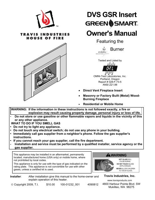
<strong>DVS</strong> <strong>GSR</strong> <strong>Insert</strong><br />
<strong>Owner's</strong> <strong>Manual</strong><br />
Featuring the<br />
Burner<br />
Tested and Listed by<br />
<br />
<br />
<br />
OMNI-Test Laboratories, Inc.<br />
Portland, Oregon<br />
Report # 028-F-73-5<br />
ANSI Z21.88<br />
Direct Vent Fireplace <strong>Insert</strong><br />
Masonry or Factory Built (Metal) Wood-<br />
Burning Fireplace<br />
Residential or Mobile Home<br />
WARNING: If the information in these instructions is not followed exactly, a fire or<br />
explosion may result causing property damage, personal injury or loss of life.<br />
- Do not store or use gasoline or other flammable vapors and liquids in the vicinity of this<br />
or any other appliance.<br />
WHAT TO DO IF YOU SMELL GAS<br />
• Do not try to light any appliance.<br />
• Do not touch any electrical switch; do not use any phone in your building.<br />
• Immediately call gas supplier from a neighbor's phone. Follow the gas supplier's<br />
instructions.<br />
• If you cannot reach your gas supplier, call the fire department.<br />
- Installation and service must be performed by a qualified installer, service agency or the<br />
gas supplier.<br />
This appliance may be installed in an aftermarket, permanently<br />
located, manufactured home (USA only) or mobile home, where<br />
not prohibited by local codes.<br />
This appliance is only for use with the type of gas indicated on the<br />
rating plate. This appliance is not convertible for use with other<br />
gases, unless a certified kit is used.<br />
Installer:<br />
After installation give this manual to the home-owner and<br />
explain operation of this heater.<br />
Copyright 2009, T.I. $10.00 100-01232_001 4090812<br />
<strong>Travis</strong> <strong>Industries</strong>, Inc.<br />
www.travisproducts.com<br />
4800 Harbour Pointe Blvd. SW<br />
Mukilteo, WA 98275
2 Introduction<br />
Introduction<br />
We welcome you as a new owner of a <strong>DVS</strong> <strong>Insert</strong>. In purchasing this fireplace insert you have joined the<br />
growing ranks of concerned individuals whose selection of an energy system reflects both a concern for<br />
the environment and aesthetics. It is one of the finest home heaters the world over. This manual will<br />
explain the installation, operation, and maintenance of this heater. Please familiarize yourself with the<br />
<strong>Owner's</strong> <strong>Manual</strong> before operating your heater and save the manual for future reference. Included are<br />
helpful hints and suggestions that will make the operation and maintenance of your new heater an easier<br />
and more enjoyable experience. We offer our continual support and guidance to help you achieve the<br />
maximum benefit and enjoyment from your heater.<br />
Important Information<br />
No other <strong>DVS</strong> <strong>Insert</strong> has the same serial number as<br />
yours. The serial number is below and to the left of the<br />
gas control valve.<br />
This serial number will be needed in case you require<br />
service of any type.<br />
Model:<br />
Serial Number:<br />
Purchase Date:<br />
Purchased From:<br />
Listing Details<br />
<strong>DVS</strong> <strong>GSR</strong> <strong>Insert</strong><br />
Register your warranty online at:<br />
traviswarranty.com<br />
Or, mail your warranty card to:<br />
<strong>Travis</strong> <strong>Industries</strong> House of Fire<br />
4800 Harbour Pointe Blvd. SW<br />
Mukilteo, WA 98275<br />
Save Your Bill of Sale.<br />
To receive full warranty coverage, you will<br />
need to show evidence of the date you<br />
purchased your heater. Do not mail your Bill<br />
of Sale to us.<br />
We suggest that you attach your Bill of Sale<br />
to this page so that you will have all the<br />
information you need in one place should the<br />
need for service or information occur.<br />
This appliance was listed by Intertek. The listing label is attached to the appliance near the gas control<br />
valve. A copy is shown on page 44.<br />
Massachusetts Approval<br />
This manual has been submitted to the Massachusetts Board of State Examiners of Plumbers and Gas<br />
Fitters.<br />
National Fireplace Institute<br />
© <strong>Travis</strong> <strong>Industries</strong> 4090812 100-01232_001
Introduction ...................................................... 2<br />
Important Information ...................................... 2<br />
Listing Details ................................................... 2<br />
Features ............................................................ 6<br />
Installation Options .......................................... 6<br />
Heating Specifications .................................... 6<br />
Dimensions ....................................................... 6<br />
Electrical Specifications .................................. 6<br />
Fuel: ................................................................... 6<br />
Installation Warnings ....................................... 7<br />
Packing List ...................................................... 7<br />
Additional Items Required .............................. 7<br />
Items Packed with the Face ............................ 7<br />
Order of Installation ......................................... 7<br />
Top Convection Deflector ............................... 8<br />
Fireplace Requirements .................................. 8<br />
Factory-Built (Metal) Wood-Burning Fireplace<br />
Requirements ........................................................ 9<br />
Hearth Requirements ....................................... 9<br />
Leveling Bolts ................................................... 9<br />
Clearances ...................................................... 10<br />
Mantel Clearances .............................................. 10<br />
Modifying the Face Connector for Discovery,<br />
Rosario, and Artisan Faces ........................... 11<br />
Face Mounting Brackets -- Arched,<br />
Metropolitan, Artisan Vict. Lace Faces ........ 12<br />
Mounting the Bedford Face .......................... 12<br />
Gas Line Requirements ................................. 13<br />
Gas Line Location ............................................... 13<br />
Gas Inlet Pressure .............................................. 13<br />
Electrical Connection .......................................... 13<br />
Vent Requirements ........................................ 14<br />
Altitude Considerations ....................................... 14<br />
Vent Restrictor .................................................... 15<br />
Vent Installation .................................................. 15<br />
Vent Location ...................................................... 16<br />
Vent Configurations............................................. 16<br />
Vent Connector Removal and Installation ........... 17<br />
Surround Panel Installation .......................... 19<br />
1-Piece Surround Panel ...................................... 20<br />
Routing the Power Cord ................................ 20<br />
Installation ..................................................... 20<br />
Glass Frame Removal and Installation ........ 21<br />
Log Set Installation ........................................ 23<br />
Ember Placement ............................................... 23<br />
Rear Log Placement ........................................... 23<br />
Left Log Placement ............................................. 24<br />
Right Log Placement ........................................... 24<br />
Right Twig Placement ......................................... 25<br />
Table of Contents 3<br />
Left Twig Placement ............................................ 25<br />
Front Ember Chunk Placement ........................... 26<br />
Rockwool Installation .......................................... 26<br />
Steps for Finalizing the Installation ............. 27<br />
Air Shutter Adjustment ........................................ 28<br />
Before You Begin ........................................... 29<br />
Remote Set-Up ............................................... 29<br />
Verify the Fan Control Module is On ................... 29<br />
Synchronize the Transmitter to the Receiver ...... 29<br />
Starting the Heater for the First Time .......... 30<br />
Location of Controls ...................................... 30<br />
Direct Operation ............................................. 31<br />
Accent Light ................................................... 32<br />
Continuous Pilot / GreenSmart Pilot Switch32<br />
Remote Operation .......................................... 33<br />
Display Overview ................................................ 33<br />
Listen for the “Beep” ........................................... 33<br />
<strong>Manual</strong> On-Off / Smart Thermostat / Standard<br />
Thermostat .......................................................... 34<br />
Mode Controls (Flame, Blower, Light, Comfort<br />
Control) ............................................................... 35<br />
Flame Height ................................................. 35<br />
Blower Speed ................................................ 35<br />
Accent Light (Aux) ......................................... 36<br />
Comfort Control (rear burner) ........................ 36<br />
Low Battery Indicator .................................... 37<br />
Transmitter Batteries ........................................... 37<br />
Receiver Batteries ............................................... 37<br />
Child Proof Feature ....................................... 37<br />
Power Outages ............................................... 37<br />
Normal Operating Sounds ............................ 38<br />
Normal Operating Odors ............................... 38<br />
Maintaining Your Heater's Appearance ....... 39<br />
Battery Replacement ..................................... 39<br />
Receiver Battery Installation ............................... 39<br />
Control Panel Light Battery ................................. 39<br />
Transmitter Battery Installation ........................... 39<br />
Accent Light Replacement............................ 40<br />
Yearly Service Procedure ............................. 40<br />
Troubleshooting Table .................................. 41<br />
Wiring Diagram .............................................. 42<br />
Replacement Parts List ................................. 43<br />
Safety Label ........................................................ 44<br />
CONDITIONS & EXCLUSIONS ...................... 45<br />
IF WARRANTY SERVICE IS NEEDED: ......... 45<br />
LP Conversion Instructions .......................... 46<br />
Firebacks ........................................................ 49<br />
Lower Surround Panel .................................. 50<br />
© <strong>Travis</strong> <strong>Industries</strong> 4090812 100-01232_001
4 Safety Precautions<br />
IF YOU SMELL GAS:<br />
* Do not light any appliance<br />
* Extinguish any open flame<br />
* Do not touch any electrical switch or plug or unplug anything<br />
* Open windows and vacate building<br />
* Call gas supplier from neighbor's house, if not reached, call fire department<br />
This unit must be installed by a qualified installer to prevent the possibility of an explosion.<br />
Your dealer will know the requirements in your area and can inform you of those people<br />
considered qualified. The room heater should be inspected and cleaned before use and<br />
at least annually by a qualified service person. More frequent cleaning may be required<br />
due to excessive lint from carpeting, bedding material, etc.<br />
The instructions in this manual must be strictly adhered to. Do not use makeshift methods<br />
or compromise in the installation. Improper installation will void the warranty and safety<br />
listing.<br />
This heater is either approved for natural gas (NG) or for propane (LP). Burning<br />
the incorrect fuel will void the warranty and safety listing and may cause an<br />
extreme safety hazard. Direct questions about the type of fuel used to your dealer.<br />
Check for a label on the flame adjust knob on the gas control valve (this is the best<br />
place to check). You may also check for a label on the gas control valve body.<br />
Ok<br />
Contact your local building<br />
officials to obtain a permit and<br />
information on any installation<br />
restrictions or inspection<br />
requirements in your area.<br />
Notify your insurance company<br />
of this heater as well.<br />
If the flame becomes sooty, dark<br />
orange in color, or extremely tall,<br />
do not operate the heater. Call<br />
your dealer and arrange for<br />
proper servicing.<br />
It is imperative that control<br />
compartments, screens, or<br />
circulating air passageways of<br />
the heater be kept clean and<br />
free of obstructions. These<br />
areas provide the air necessary<br />
for safe operation.<br />
?<br />
Do<br />
not operate the heater if it is<br />
not operating properly in any<br />
fashion or if you are uncertain.<br />
Call your dealer for a full<br />
explanation of your heater and<br />
what to expect.<br />
Gas<br />
Do not store or use gasoline or<br />
other flammable liquids in the<br />
vicinity of this heater.<br />
<br />
<br />
Do not operate if any portion of<br />
the heater was submerged in<br />
water or if any corrosion occurs.<br />
Immediately call a qualified<br />
service technician to inspect the<br />
appliance and to replace any part<br />
of the control system that has<br />
been under water.<br />
© <strong>Travis</strong> <strong>Industries</strong> 4090812 100-01232_001
Safety Precautions 5<br />
• Do not place clothing or<br />
other flammable items on or<br />
near the heater. Because<br />
this heater can be controlled<br />
by a thermostat there is a<br />
possibility of the heater<br />
turning on and igniting any<br />
items placed on or near it.<br />
• The viewing glass should be<br />
opened only for lighting the<br />
pilot or conducting service.<br />
• Any safety screen or guard<br />
removed for servicing must<br />
be replaced prior to<br />
operating the heater.<br />
• Do not operate with the<br />
glass removed or damaged.<br />
• Operate the heater<br />
according to the instructions<br />
included in this manual.<br />
• If the main burners do not<br />
start correctly turn the gas<br />
off at the gas control valve<br />
and call your dealer for<br />
service.<br />
<br />
<br />
<br />
• Light the heater using the<br />
built-in igniter. Do not use<br />
matches or any other<br />
external device to light your<br />
heater.<br />
• Allow the heater to cool<br />
before carrying out any<br />
maintenance or cleaning.<br />
• Never remove, replace,<br />
modify or substitute any part<br />
of the heater unless<br />
instructions are given in this<br />
manual. All other work must<br />
be done by a trained<br />
technician. Don't modify or<br />
replace orifices.<br />
• Instruct everyone in the<br />
house how to shut gas off to<br />
the appliance and at the gas<br />
main shutoff valve. The gas<br />
main shutoff valve is usually<br />
next to the gas meter or<br />
propane tank and requires a<br />
wrench to shut off.<br />
<br />
<br />
• This unit is not for use with<br />
solid fuel<br />
• Do not place anything inside<br />
the firebox (except the<br />
included fiber logs).<br />
• If the fiber logs become<br />
damaged, replace with<br />
<strong>Travis</strong> <strong>Industries</strong> log set.<br />
• Children and adults should<br />
be alerted to the hazards of<br />
high surface temperature<br />
and should stay away to<br />
avoid burns or clothing<br />
ignition. Young children<br />
should be supervised when<br />
they are in the same room<br />
as the heater.<br />
This<br />
<strong>Manual</strong><br />
• Do not throw this manual<br />
away. This manual has<br />
important operating and<br />
maintenance instructions<br />
that you will need at a later<br />
time. Always follow the<br />
instructions in this manual.<br />
• Plug the heater into a 120V<br />
grounded electrical outlet.<br />
Do not remove the<br />
grounding plug.<br />
• Don’t route the electrical<br />
cord in front of, over, or<br />
under the heater<br />
• <strong>Travis</strong> <strong>Industries</strong>, Inc.<br />
grants no warranty,<br />
implied or stated, for the<br />
installation or<br />
maintenance of your<br />
heater, and assumes no<br />
responsibility of any<br />
consequential damage(s).<br />
© <strong>Travis</strong> <strong>Industries</strong> 4090812 100-01232_001
6 Features and Specifications<br />
Features<br />
- Ember Fyre Burner for "Wood Fire" Look<br />
- Works During Power Outages (battery backup system)<br />
- Blower and Remote Control Included<br />
- Standing or Intermittent (GreenSmart) Pilot<br />
- Convenient Operating Controls<br />
- Variable-Rate Heat Output<br />
- Accent Light<br />
Heating Specifications<br />
Installation Options<br />
<br />
<br />
<br />
Residential or Mobile Home<br />
Fireplace <strong>Insert</strong><br />
Masonry or Factory Built (Metal) Wood-<br />
Burning Fireplace<br />
Natural Gas<br />
Propane<br />
Approximate Heating Capacity (in square feet)* 500 to 1,500 500 to 1,500<br />
Maximum BTU Input Per Hour 31,000 31,000<br />
* Heating capacity will vary with floor plan, insulation, and outside temperature.<br />
Dimensions<br />
See the section "Vent Requirements"<br />
for vent location.<br />
25"*<br />
4x6 Panels<br />
28-7/8"*<br />
8x10 Panels<br />
18"<br />
31-7/8"*<br />
10x13 Panels<br />
19-1/2"<br />
26-1/2"<br />
Weight:<br />
115 Lbs.<br />
* Includes trim<br />
37-1/8"* 4x6 Panels<br />
40-3/8"* 8x10 Panels<br />
44-3/8"* 10x13 Panels<br />
NOTE: on older style panels the 3/8" standoffs<br />
are no longer required and may be bent back.<br />
1-1/4"*<br />
15-1/8"<br />
Electrical Specifications<br />
Fuel<br />
Electrical Rating ............................................................. 115 Volts, 1.5 Amps, 60 Hz (180 watt)<br />
This heater is shipped in natural gas (NG) configuration but may be converted to propane (LP) using<br />
a conversion kit. The sticker on top of the gas control valve will verify the correct fuel.<br />
© <strong>Travis</strong> <strong>Industries</strong> 4090812 100-01232_001
Installation Warnings<br />
<br />
<br />
<br />
<br />
<br />
<br />
<br />
<br />
Installation (for qualified installers only) 7<br />
Failure to follow all of the requirements may result in property damage, bodily<br />
injury, or even death.<br />
This heater must be installed by a qualified installer who has gone through a<br />
training program for the installation of direct vent gas appliances.<br />
This appliance must be installed in accordance with all local codes, if any; if<br />
not, follow ANSI Z223.1 and NFPA 54(88).<br />
In Manufactured or Mobile Homes must conform with Manufactured Home<br />
Construction and Safety Standard, Title 24 CFR, Part 3280, or, when such a<br />
standard is not applicable, the Standard for Manufactured Home Installations,<br />
ANSI/NCSBCS A225.1. This appliance may be installed in Manufactured<br />
Housing only after the home is site located.<br />
The heater is designed to operate on natural gas, or propane (LP).<br />
All exhaust gases must be vented outside the structure of the living-area.<br />
Combustion air is drawn from outside the living-area structure.<br />
Notify your insurance company before hooking up this heater.<br />
The requirements listed below are divided into sections. All requirements<br />
must be met simultaneously. The order of installation is not rigid – the<br />
qualified installer should follow the procedure best suited for the installation.<br />
Packing List<br />
<br />
<br />
<br />
<br />
LP Orifices and Orifice Gaskets<br />
Log Set<br />
Cove Covers<br />
Panel Trim Rectangular & Button Plug (see page<br />
Error! Bookmark not defined.)<br />
Additional Items Required<br />
<br />
<br />
<br />
"Fireplace Altered" tag (attach to the fireplace)<br />
Remote Control<br />
Cover Plate for Receiver (with screws)<br />
If using lp (propane) a conversion kit is required (sku 94400999 – <strong>GSR</strong> Stepper Motor Kit)<br />
Faceplate<br />
Simpson Duravent 6-5/8" to 3" & 3" Co-Linear Adapter with flashing<br />
3" Diameter Gas Liner (2)<br />
Direct Vent Cap (Use Simpson Duravent High Wind Cap)<br />
Gas Line Equipment (shutoff valve, pipe, etc.)<br />
Items Packed with the Face<br />
<br />
<br />
Face with attachment hardware (Note: use the cove covers included with the heater)<br />
Face Installation Instructions<br />
Order of Installation<br />
1 If the heater is to use LP (propane), convert the appliance (see page 46).<br />
2 Install gas line into the fireplace (do not connect to unit).<br />
3 Position the heater.<br />
4 Connect the gas line and gas vent to the appliance.<br />
5 Install the optional surround panels and trim. Attach the on/off switch.<br />
6 Follow the instructions under "Finalizing the Installation" on page 27.<br />
© <strong>Travis</strong> <strong>Industries</strong> 4090812 100-01232_001
8 Installation (for qualified installers only)<br />
Top Convection Deflector<br />
Install the top convection deflector as<br />
shown to the right.<br />
The deflector is shipped on top of the<br />
insert. The screws are shipped inside<br />
the owner's pack.<br />
Fireplace Requirements<br />
<br />
<br />
<br />
<strong>Insert</strong> must be placed within a code-conforming masonry fireplace or tested and listed factory-built<br />
(metal) wood-burning fireplace. Repair any fireplace damage prior to installation.<br />
Because the insert uses a circulation blower, clean the fireplace, smoke shelf, and chimney prior to<br />
installation.<br />
This heater may be placed in a bedroom. Please be aware of the large amount of heat this appliance<br />
produces when determining a location.<br />
a<br />
f<br />
b<br />
Fireplace Sizing 3-Piece Panel 1-Piece Panel<br />
a Minimum Height 19-1/2” (496mm) 20-5/8” (524mm)<br />
b Minimum Width 26-1/2” (674mm) 29” (737mm)<br />
c Minimum Depth 15-1/8” (385mm) 16-3/8” (416mm)<br />
d Hearth Extension 1-1/4” (32mm) 0” (0mm)<br />
e<br />
c<br />
g<br />
h<br />
e<br />
f<br />
The gas and electrical line should be installed prior to<br />
installing the heater.<br />
For tight fits (under 24”) see the section “Removing the<br />
Vent Connector”<br />
d<br />
g See “Leveling Bolts” for details on leveling the heater.<br />
h Attach the “This fireplace has been altered…” plate to the fireplace (use two screws or other<br />
suitable method). You may wish to place it in a location where it will be covered by the surround panels.<br />
© <strong>Travis</strong> <strong>Industries</strong> 4090812 100-01232_001
Installation (for qualified installers only) 9<br />
Factory-Built (Metal) Wood-Burning Fireplace Requirements<br />
NOTE: Any parts that are removed must be removed in a way that would allow them to be re-installed if<br />
the insert is ever removed (removal of rivets or screws is acceptable).<br />
The damper ("A") and grate (with log set) ("B") must be removed (see the illustration below)<br />
The smoke shelf ("C"), internal baffles ("D"), screen ("E"), masonry lining or refractory ("G" & "I"), and<br />
metal or glass doors ("F") may be removed (if applicable)<br />
The fireplace must be permanently marked to <br />
H<br />
indicate that it has been altered and is no longer<br />
suitable for burning solid fuel (wood), unless the <br />
removed parts are re-installed. Cutting of any<br />
<br />
A<br />
sheet metal parts is prohibited, except the metal F<br />
C<br />
floor (“J”) as noted below.<br />
The insulation ("H"), and any structured rigid frame<br />
members must not be removed or altered (side and<br />
top of door frame, side and top of the face of the<br />
fireplace, metal sides, etc.).<br />
<br />
<br />
<br />
D<br />
E<br />
I<br />
The metal floor ("J") may be removed to allow<br />
B<br />
additional room for installation of the insert. If the<br />
<br />
floor is removed the insert must be placed directly<br />
G<br />
on the metal base of the metal fireplace.<br />
Hearth Requirements<br />
<br />
J<br />
<br />
<br />
The heater and face must not contact combustible surfaces. A non-combustible hearth extension is not<br />
required. However, if the heater is installed next to the floor, we recommend a hearth to protect the<br />
flooring surface from discoloration or other negative impact from the heater.<br />
Leveling Bolts<br />
This heater includes<br />
front and rear leveling<br />
bolts to accommodate<br />
fireplaces with a stepdown<br />
firebox.<br />
NOTE: To access the<br />
rear leveling bolts,<br />
remove the burner (see<br />
page 49).<br />
<br />
<br />
<br />
<br />
To access the rear leveling bolts remove these<br />
access plates (replace access plate and<br />
gasket after adjustment).<br />
<br />
<br />
<br />
<br />
Use a 1/2” socket wrench<br />
(with extension) to adjust<br />
the leveling bolts.<br />
Rear Leveling Bolt<br />
Front Leveling Bolts<br />
© <strong>Travis</strong> <strong>Industries</strong> 4090812 100-01232_001
10 Installation (for qualified installers only)<br />
Clearances<br />
Due to the high temperature of the heater, it should be located out of traffic and away from furniture and<br />
draperies.<br />
Combustible or Non-Combustible Mantel<br />
<br />
<br />
<br />
<br />
Side<br />
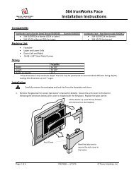
Wall<br />
k<br />
n<br />
<br />
<br />
<br />
m<br />
<br />
<br />
l<br />
<br />
<br />
x<br />
<br />
\ <br />
<br />
Mantel Clearances<br />
Combustible Top Facing<br />
Non-Combustible<br />
Facing<br />
Minimum<br />
Clearances<br />
k Sidewall to <strong>Insert</strong> 4-1/2"<br />
115mm<br />
l Side Facing<br />
(non-combustible)<br />
m Top Facing<br />
(non-combustible)<br />
n Mantel<br />
(combustible or<br />
non-combustible)<br />
x Hearth Extension<br />
(3-Piece Panel)<br />
x Hearth Extension<br />
(1-Piece Panel)<br />
4-1/2"<br />
115mm<br />
35"<br />
889mm<br />
35"<br />
889mm<br />
1-1/4"<br />
32mm<br />
0"<br />
0mm<br />
The maximum mantel depth is 12”.<br />
NOTE: The combustible area above the facing must not protrude more than 3/4" from the facing. If it<br />
does, it is considered a mantel and must meet the mantel requirements listed in this manual.<br />
© <strong>Travis</strong> <strong>Industries</strong> 4090812 100-01232_001
Installation (for qualified installers only) 11<br />
Modifying the Face Connector for Discovery, Rosario, and Artisan Faces<br />
The Discovery, Rosario, and Artisan face require re-positioning of the face connector. See the directions<br />
below for details.<br />
Remove the face connector bracket<br />
from the heater (on both sides).<br />
Re-attach the face connector to the<br />
heater using the forward mounting holes.<br />
Face Connector<br />
Bracket<br />
© <strong>Travis</strong> <strong>Industries</strong> 4090812 100-01232_001
12 Finalizing the Installation<br />
Face Mounting Brackets -- Arched, Metropolitan, Artisan Vict. Lace Faces<br />
Some Arched, Artisan, Metropolitan, and Victorian Lace Faces include old brackets that will not mount to<br />
the heater (see illustration below). For these faces, make sure to use the new mounting brackets (either<br />
included with the heater or available through your dealer - SKU 250-00519).<br />
WARNING: When attaching the Victorian Lace Face, do not over-tighten the screws. Over-tightening<br />
the screws may damage the face – simply tighten the screws until they contact the face.<br />
Old Arched,<br />
Metropolitan, or<br />
Artisan Bracket<br />
Old Victorian<br />
Lace<br />
Bracket<br />
New<br />
Bracket<br />
NOTE: The brackets<br />
install with this pair of<br />
closely spaced<br />
flanges at the top.<br />
Install the face mounting brackets to<br />
the heater with the included nuts.<br />
NOTE: The face attaches to the brackets with the screws included with the face – see the instructions<br />
included with the face.<br />
Mounting the Bedford Face<br />
Some Bedford Faces include old brackets that will<br />
not mount to the heater. For these faces, make<br />
sure to use the new <strong>DVS</strong> <strong>Insert</strong> EF II Face<br />
Upgrade Kit (either included with the face or<br />
available through your dealer - SKU 250-00029).<br />
The kit lowers the face and surround panels 1-1/4”.<br />
This means you must install this with a raised<br />
fireplace or raise the insert 1-1/4” above the hearth.<br />
To do this you may extend the leveling bolts or<br />
place bricks or other non-combustible under the<br />
insert.<br />
1-1/4”<br />
© <strong>Travis</strong> <strong>Industries</strong> 4090812 100-01232_001
Gas Line Requirements<br />
MASSACHUSETTS INSTALLATIONS - WARNING:<br />
Finalizing the Installation 13<br />
THIS PRODUCT MUST BE INSTALLED BY A LICENSED PLUMBER OR GAS FITTER WHEN INSTALLED WITHIN THE<br />
COMMONWEALTH OF MASSACHUSETTS.<br />
OTHER MASSACHUSETTS CODE REQUIREMENTS:<br />
<br />
<br />
<br />
<br />
<br />
Flexible connector must not be longer than 36 inches.<br />
Shutoff valve must be a “T” handle gas cock.<br />
Only direct vent sealed combustion products are approved for bedrooms or bathrooms.<br />
Fireplace dampers must be removed or welded in the open position prior to the installation of a fireplace insert or gas log.<br />
A carbon monoxide (CO) detector is required in the same room as the appliance.<br />
<br />
<br />
<br />
<br />
<br />
<br />
The gas line must be installed in accordance with all local codes, if any; if not, follow ANSI 223.1 and<br />
the requirements listed below.<br />
A manual shutoff valve is required within 3’ of the heater. It should be placed upstream of the flex<br />
line (if used) and may be installed behind the access door inside the heater. ).<br />
The heater and gas control valve must be disconnected from the gas supply piping during any<br />
pressure testing of that system at test pressures in excess of 1/2 psig. For pressures under 1/2 psig,<br />
isolate the gas supply piping by closing the manual shutoff valve.<br />
Leak test all gas line joints and the gas control valve prior to and after starting the heater.<br />
This heater is designed either for natural gas or for propane (but not for both). Check the sticker on<br />
the top of the gas control valve to make sure the correct fuel is used (see illustration on page 4).<br />
Installation must be performed by a qualified installer, service agency or the gas supplier (In<br />
Massachusetts a licensed plumber/gasfitter).<br />
Gas Line Location<br />
The gas inlet<br />
accepts a 1/2" MPT.<br />
Shutoff Valve (secured to<br />
the fireplace insert)<br />
Fireplace Opening<br />
2-3/4"<br />
Gas Inlet Pressure<br />
<br />
<br />
Natural Gas<br />
Propane<br />
Standard Input Pressure<br />
7" W.C. (1.74 kPA)<br />
13" W.C. (2.73 kPA)<br />
If the pressure is not sufficient, make sure the piping used is large enough, the supply regulator is<br />
adequately adjusted, and the total gas load for the residence does not exceed the amount supplied.<br />
The supply regulator (the regulator that attaches directly to the residence inlet or to the propane tank)<br />
should supply gas at the suggested input pressure listed above. Contact the local gas supplier if the<br />
regulator is at an improper pressure.<br />
Electrical Connection<br />
<br />
<br />
Route the power cord out of the access hole on the right side of the appliance.<br />
Plug the power cord into a grounded 120 Volt outlet (do not remove the grounding pin).<br />
The electrical connection may also be made using the optional Wiring Kit (SKU 97200315).<br />
© <strong>Travis</strong> <strong>Industries</strong> 4090812 100-01232_001
14 Finalizing the Installation<br />
Vent Requirements<br />
<strong>Travis</strong> <strong>Industries</strong> manufactures a<br />
vent kit specifically for this insert<br />
(sku 96200330). It includes 30’<br />
(10M) of vent, hose clamps, and a<br />
prairie cap. The flashing on the cap<br />
is 18” (458mm) by 18” (458mm).<br />
<br />
<br />
<br />
<br />
<br />
<br />
The gas appliance and vent system must be vented directly to the outside of the building, and never<br />
be attached to a chimney serving a separate solid fuel or gas-burning appliance. Each direct vent<br />
gas appliance must use its own separate vent system.<br />
Make sure the exhaust pipe on the heater connects to the exhaust portion of the cap. The<br />
illustrations below show how the flex liners should be attached.<br />
The exhaust vent must reline the entire length of the chimney and terminate above the chimney top.<br />
Be careful not to crimp or rupture the liner when bending it into chimney offsets.<br />
When installed, the vent must meet all of the vent manufacturer's requirements.<br />
Make sure to use the following:<br />
3” UL 441 or 1777 Gas Liner for Exhaust and Air Inlet<br />
Simpson Duravent 6-5/8” to 3” & 3” Co-Linear Adapter and Flashing<br />
Simpson Duravent High-Wind Vertical Termination Cap (46DVA-VCH) or Prairie Cap<br />
Max. Ht. 40'<br />
Min. Ht. 8'<br />
Exhaust<br />
(3" dia.)<br />
<br />
<br />
<br />
<br />
<br />
<br />
<br />
Inlet<br />
(3" dia.)<br />
Max. 2'<br />
offset<br />
Altitude Considerations<br />
<br />
<br />
This heater has been tested at altitudes ranging from sea level to 8,000 feet (2,400 M). In this testing<br />
we have found that the heater, with its standard orifice, burns correctly with just an air shutter<br />
adjustment.<br />
Failure to adjust the air shutter properly may lead to improper combustion which can create a safety<br />
hazard. Consult your dealer or installer if you suspect an improperly adjusted air shutter.<br />
© <strong>Travis</strong> <strong>Industries</strong> 4090812 100-01232_001
Finalizing the Installation 15<br />
Vent Restrictor<br />
WARNING: Restrictor adjustment should only be done by a qualified installer.<br />
Only those installations determined to be over-drafting require this adjustment. The best indication of<br />
over-drafting is a hyper-active flame pattern (flames that move too quickly). If the air shutter is<br />
constricted, the flames become short and yellow, yet still very active. Over-drafting may affect the pilot,<br />
but this is not the best way to determine over-drafting. Over-drafting is most likely in tall venting<br />
configurations (especially if using an “Exhaust Only Re-Line”). Do not over-restrict the vent (this leads to<br />
ghosting or lifting flames - reduce restrictor setting).<br />
To Access the Restrictor:<br />
Remove the face.<br />
WARNING: Use a glove to protect<br />
your hand from burns.<br />
To Adjust the Restrictor:<br />
1<br />
2<br />
Determine a restrictor position. Start low (move<br />
the restrictor a maximum two positions at a time)<br />
and thoroughly test the heater before adjusting further.<br />
Lift up the adjustment plate and move it so the correct notch falls<br />
into the slot on the adjustment bracket.<br />
Adjustment<br />
Plate<br />
#4 #5 #6<br />
#3<br />
#2<br />
#1<br />
Adjustment<br />
Bracket<br />
This restrictor is in position 1<br />
(factory setting).<br />
Vent Installation<br />
To adjust, lift up on the<br />
adjustment plate and push it back<br />
(use pliers if necessary).<br />
This restrictor is in<br />
position 2.<br />
Exhaust (3")<br />
Inlet (3")<br />
3" dia. Gas Liner<br />
High Wind<br />
Termination Cap<br />
Simpson Duravent<br />
6-5/8" to 3" & 3"<br />
Co-Linear Adapter<br />
Use hose-clamps to<br />
secure the vent.<br />
Alternative Method: use<br />
high-temperature<br />
silicone and secure with<br />
screws.<br />
<br />
<br />
<br />
Exhaust<br />
Inlet<br />
<br />
Use hose-clamps<br />
to secure the vent.<br />
Alternative Method: use high-temperature<br />
silicone and secure with screws.<br />
<br />
© <strong>Travis</strong> <strong>Industries</strong> 4090812 100-01232_001
16 Finalizing the Installation<br />
Vent Location<br />
<br />
A vent restrictor is built into the appliance to adjust the flow rate of exhaust gases. This ensures<br />
proper combustion for all vent configurations. Depending upon the vent configuration, you may be<br />
required to adjust the restrictor position.<br />
NOTE: Vent location changes based<br />
upon restrictor position. Position # 1 is<br />
shown to the right. Each restrictor<br />
position moves the vent location forward<br />
(toward the fireplace opening)<br />
approximately 1/4”.<br />
Exhaust (3” Dia.)<br />
6-1/8”<br />
1-1/4”<br />
Center Line<br />
1-1/4”<br />
Inlet (3” Dia.)<br />
2-5/8”<br />
15-1/8”<br />
Fireplace<br />
Opening<br />
Vent Configurations<br />
Inlet & Exhaust Re-Line<br />
Exhaust Only Re-Line<br />
Direct Vent Cap<br />
Exhaust<br />
3" dia.<br />
Gas Liner<br />
<br />
<br />
<br />
<br />
<br />
<br />
<br />
<br />
<br />
<br />
<br />
<br />
<br />
Factory Built (Metal) Wood-<br />
Burning Fireplace<br />
Recommended Block-Off<br />
Plate (non-combustible<br />
metal and/or insulation).<br />
Prevents odors from<br />
chimney entering room.<br />
<br />
<br />
<br />
<br />
<br />
<br />
<br />
<br />
<br />
<br />
<br />
<br />
<br />
<br />
<br />
<br />
<br />
<br />
<br />
<br />
<br />
<br />
<br />
<br />
Masonry <br />
Fireplace<br />
<br />
6-5/8" to 3" & 3" Colinear<br />
Adapter & Flashing<br />
Inlet<br />
3" dia. Gas Liner<br />
Any cracks or<br />
damage inside the<br />
chimney must be<br />
repaired.<br />
A block-off plate must<br />
seal the intake to the<br />
chimney space. This<br />
way air is drawn down<br />
the chimney for<br />
combustion air.<br />
Block-Off Plate<br />
(non-combustible<br />
materials)<br />
Inlet<br />
Exhaust<br />
3" dia. Gas Liner<br />
NOTE: You may use either re-line configuration with a masonry or zero-clearance fireplace.<br />
© <strong>Travis</strong> <strong>Industries</strong> 4090812 100-01232_001
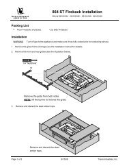
Vent Connector Removal and Installation<br />
Finalizing the Installation 17<br />
The vent connector is shipped attached to the insert, but may be removed to facilitate tight<br />
installations. See the directions below for installation.<br />
1. Route the flex vent through the chimney from above (leave an extra 3' at the top). Make sure the flex<br />
is thoroughly stretched.<br />
2. Remove the vent connector and attach it to the flex vent (see the instructions on the following page).<br />
NOTE: be careful of the anti-seize on the connector – it will stain clothing, etc.<br />
3. Pull on the flex vent until the vent connector is at the same height as the insert. Temporarily attach<br />
the flex vent to the top of the chimney (leave extra slack).<br />
4. Slide the insert into place, guiding the vent connector into the guides on top of the insert.<br />
5. Attach the vent connector to the appliance (see the following page for details).<br />
6. Remove any excess slack in the flex line and attach the vent termination.<br />
<br />
<br />
1<br />
<br />
3<br />
6<br />
<br />
<br />
<br />
<br />
<br />
<br />
<br />
<br />
<br />
<br />
<br />
<br />
<br />
<br />
<br />
<br />
<br />
<br />
<br />
<br />
<br />
<br />
<br />
<br />
<br />
<br />
<br />
<br />
<br />
<br />
<br />
<br />
<br />
<br />
<br />
<br />
<br />
<br />
<br />
<br />
<br />
<br />
<br />
<br />
<br />
<br />
<br />
<br />
<br />
<br />
<br />
<br />
<br />
<br />
<br />
<br />
<br />
<br />
<br />
<br />
<br />
<br />
<br />
<br />
<br />
<br />
<br />
<br />
<br />
<br />
<br />
<br />
<br />
<br />
<br />
<br />
<br />
<br />
<br />
<br />
<br />
<br />
<br />
<br />
5<br />
<br />
2<br />
4<br />
<br />
<br />
2<br />
<br />
<br />
<br />
<br />
<br />
<br />
<br />
<br />
<br />
<br />
<br />
<br />
<br />
© <strong>Travis</strong> <strong>Industries</strong> 4090812 100-01232_001
18 Finalizing the Installation<br />
Vent Connector Removal and Installation (continued)<br />
Vent Connector Removal<br />
Pull the vent connector<br />
rod forward.<br />
WARNING: The anti-seize on<br />
the vent connector can stain<br />
clothing, carpets, or other<br />
items.<br />
Slide the<br />
connector to the<br />
rear. It will<br />
"snap" out.<br />
Vent Connector Installation<br />
Attach the flex vent to<br />
the vent connector.<br />
<br />
<br />
<br />
<br />
Slide the insert<br />
into place, lining<br />
up these guides<br />
with the edges of<br />
the vent<br />
connector.<br />
<br />
<br />
<br />
<br />
<br />
Push the vent<br />
connector rod in, lift<br />
slightly, and line it up<br />
so the tabs on the end<br />
of the rod engage the<br />
hooks on the vent<br />
connector<br />
<br />
<br />
Pull on the vent connector rod until the<br />
vent connector snaps into place. Slide<br />
the vent connector rod in to conceal it.<br />
© <strong>Travis</strong> <strong>Industries</strong> 4090812 100-01232_001
Surround Panel Installation<br />
Finalizing the Installation 19<br />
PANEL SIZE WIDTH HEIGHT PART #<br />
8” x 10” Rectangular 40-3/8” 28-7/8” 96100301<br />
Arched (8" x 10") 40-3/8” 28-7/8” 98500605<br />
10” x 13” Rectangular 44-3/8” 31-7/8” 96100302<br />
4” x 6” Rectangular 37-1/8” 25” 96100300<br />
NOTE: The insert may be installed without surround panels.<br />
NOTE: The insert may be installed<br />
without surround panels.<br />
a<br />
Pre-thread the holes on the surround<br />
panels with the screws included in the<br />
surround panel kit.<br />
5/16" Nutdriver<br />
1 Follow the directions to the<br />
right to install the side panels.<br />
2 Follow the directions below to<br />
install the top panel.<br />
b<br />
Line up each side surround<br />
panel and insert two screws from<br />
the inside to secure in place.<br />
Run the power cord to<br />
the right of the insert.<br />
<br />
<br />
Top<br />
Panel<br />
Top Trim<br />
Spring<br />
Clips<br />
b<br />
Top Trim<br />
"L" Bracket<br />
<br />
Micro (1/16”)<br />
Standard<br />
Screwdriver<br />
COVER PLUGS FOR<br />
ON/OFF SWITCH AND<br />
RHEOSTAT<br />
Install the button plug<br />
and switch plug into the<br />
surround panel trim to<br />
conceal the mounting<br />
holes (see the<br />
illustration below).<br />
<br />
"L" Bracket<br />
Right Side<br />
Trim<br />
Trim Installation:<br />
<strong>Insert</strong> one leg of each "L" bracket into the top<br />
and side trim piece. Align the trim to form a<br />
a<br />
Install the top panel so<br />
Right Side Trim<br />
precise corner, then tighten the two set<br />
screws with a small standard screwdriver.<br />
Slide the trim over the panels. Place the<br />
the tabs insert into the<br />
spring clips behind the panels at the locations<br />
joggle clips on the top<br />
shown. This keeps the trim tight against the<br />
panel<br />
panel.<br />
Optional Knock-Out<br />
An optional knock-out is provided if the power cord is<br />
routed behind the surround panel.<br />
© <strong>Travis</strong> <strong>Industries</strong> 4090812 100-01232_001
20 Finalizing the Installation<br />
1-Piece Surround Panel<br />
<strong>DVS</strong> – 25” by 38” 96100318<br />
<strong>DVS</strong> – 28-1/2” by 40” 96100324<br />
NOTE: The panels may be cut down in size and placed within the fireplace opening.<br />
Routing the Power Cord<br />
Because this panel fits flush against the fireplace facing, the panel does not have a notch allowing the power<br />
cord to exit the fireplace. We recommend using the insert wiring kit (sku 97200315) to route power to the<br />
insert. Otherwise, route the power cord behind the panel to the right side (the panel or fireplace may be<br />
notched, if required).<br />
Installation<br />
1. Attach the mounting brackets as shown below.<br />
2. Attach the surround panel as shown below.<br />
© <strong>Travis</strong> <strong>Industries</strong> 4090812 100-01232_001
Glass Frame Removal and Installation<br />
Finalizing the Installation 21<br />
Warning:<br />
Warning:<br />
The appliance must be completely cool before removing the glass.<br />
Do not strike or slam the glass.<br />
a<br />
Open the four latches holding the glass<br />
frame in place (start with the two below<br />
the glass) - follow the directions shown<br />
to the right.<br />
Top of<br />
Firebox<br />
Latch<br />
Push in on<br />
the latch.<br />
Glass<br />
Twist 1/4 turn.<br />
b<br />
Glass Frame<br />
Lift the glass frame up<br />
and pull it forward to<br />
remove. NOTE:<br />
You may need to lift the<br />
glass frame while reattaching.<br />
NOTE:<br />
Replace the cove<br />
covers for those faces<br />
using them.<br />
Re-Attaching the Glass Frame:<br />
a) Hang the glass frame on the firebox.<br />
b) While holding in place, attach the upper latches<br />
(follow the instructions to the right in reverse).<br />
c) Lift the glass frame slightly and attach the lower latches.<br />
The latch will then<br />
disengage from the<br />
latch bracket.<br />
© <strong>Travis</strong> <strong>Industries</strong> 4090812 100-01232_001
22 Finalizing the Installation<br />
Glass Frame Removal and Installation (continued)<br />
The glass latch can come loose from the glass frame. This occurs when the latch is turned 1/8 turn when<br />
disengaged from the unit. Follow the directions below to re-install the latch if it comes loose.<br />
Latch<br />
Hold the latch at an angle and<br />
insert it into the slot on the<br />
glass frame. Note how the<br />
washer fits in front of the flange<br />
on the glass frame. You will<br />
need to push slightly to get the<br />
latch to insert.<br />
Glass<br />
Once fully inserted, turn<br />
the latch until it is is level.<br />
© <strong>Travis</strong> <strong>Industries</strong> 4090812 100-01232_001
Finalizing the Installation 23<br />
Log Set Installation<br />
! The logs are fragile, especially after being exposed to heat.<br />
<br />
<br />
Make sure the gas control valve is “OFF” and the heater is cool prior to conducting service.<br />
Failure to position the parts in accordance with these diagrams or failure to use only parts<br />
specifically approved with this appliance may result in property damage or personal injury.<br />
If using propane (LP), convert the appliance before installing the logs (see page 46).<br />
<br />
Ember Placement<br />
The burner must be correctly positioned before installing the logs. Make sure the burner is fully<br />
seated and the pilot is properly aligned. See page 46 for details on burner removal.<br />
Place a layer of embers along any visible edges of the burner.<br />
Rear Log Placement<br />
The rear log has two holes on the bottom. Place the log so the pins on the burner insert into the<br />
holes on the log (see photos below).<br />
© <strong>Travis</strong> <strong>Industries</strong> 4090812 100-01232_001
24 Finalizing the Installation<br />
Left Log Placement<br />
The left log has two holes on the bottom. Place the log so the pin on the burner and the metal<br />
bracket insert into the holes on the log (see photos below).<br />
Right Log Placement<br />
The right log has two holes on the bottom. Place the log so the pin on the burner and the metal<br />
bracket insert into the holes on the log (see photos below).<br />
© <strong>Travis</strong> <strong>Industries</strong> 4090812 100-01232_001
Finalizing the Installation 25<br />
Right Twig Placement<br />
The right twig has a single hole in the bottom that fits over the right pin on the back log (see photos<br />
below). The lower side of the twig rests on the right log. Place the twig as shown below.<br />
Left Twig Placement<br />
The left twig has two holes in the bottom of it – for this model, place the log so the left pin on the<br />
rear log inserts into the lower hole (see photo below). The bottom of the log rests on the left log.<br />
Place the log as shown below.<br />
© <strong>Travis</strong> <strong>Industries</strong> 4090812 100-01232_001
26 Finalizing the Installation<br />
Front Ember Chunk Placement<br />
This log set includes a left, center, and right-side ember chunk (see photo below).<br />
Left Ember Chunk Center Ember Chunk Right Ember Chunk<br />
Place the ember chunks as shown in the photos below. Make sure the ember chunks do not cover<br />
any burner holes.<br />
Right Side Ember Chunk<br />
Center Ember Chunk<br />
Left Side Ember Chunk<br />
Rockwool Installation<br />
The included rock wool is placed on top of the burner to enhance the glow from the burner. The rock<br />
wool works best when it is applied in a very thin, porous layer. The best method for applying the<br />
rock wool is to brush it on to the burner. Compress a clump of rockwool between your thumb and<br />
forefinger. Use a stiff brush to apply a thin layer of rockwool fibers onto the burner. Do not use the<br />
entire bag of rockwool. Use only a small amount and save the remainder. Over-use of rockwool will<br />
diminish the glow and may cause sooting or other adverse conditions.<br />
© <strong>Travis</strong> <strong>Industries</strong> 4090812 100-01232_001
Steps for Finalizing the Installation<br />
1. Remove the glass (see page 21).<br />
NOTE:<br />
Finalizing the Installation 27<br />
If using propane (LP) convert the appliance prior to installing the logs.<br />
2. We recommend you purge the gas line at this time (with the glass removed). This allows gas to be detected<br />
once it enters the firebox, ensuring gas does not build up.<br />
3. Make sure the accent light bulb is in place.<br />
NOTE: Take care to not touch the bulb with your fingers – use a cloth or paper towel).<br />
4. Install the four AA batteries and receiver cover (included in the owner’s pack - see illustration below). The AA<br />
batteries act as a power backup in case the household (AC) power goes out and are required for operation.<br />
Install the 9v battery (included in the owner’s pack) into the battery holder (see illustration below). This battery is<br />
for the control panel lights. Install three AAA batteries into the remote (see illustration below). Synchronize the<br />
transmitter to the receiver (see page 29).<br />
Battery Holder for<br />
Control Panel Lights<br />
OFF<br />
HIGH<br />
CONTINUOUS<br />
PILOT<br />
ON REMOTE OFF<br />
PRG<br />
9v<br />
Battery<br />
LOW<br />
ACCENT LIGHT<br />
GREEN SMART<br />
PILOT<br />
The remote receiver<br />
uses 4 AA batteries.<br />
°F<br />
AA Battery<br />
AA Battery<br />
AA Battery<br />
AA Battery<br />
The remote<br />
uses 3 AAA<br />
batteries.<br />
AAA Battery<br />
AAA Battery<br />
AAA Battery<br />
© <strong>Travis</strong> <strong>Industries</strong> 4090812 100-01232_001
28 Finalizing the Installation<br />
5. Install the logs (see page 23).<br />
6. Replace the glass.<br />
7. Start the heater.<br />
8. Leak test all gas joints.<br />
9. Check the air shutter following the directions below.<br />
Air Shutter Adjustment<br />
Let the heater burn for fifteen minutes (make sure the logs and glass are in place). The flames should be<br />
yellow with no sooting. Adjust the air shutter, if necessary, to achieve the correct looking flame.<br />
Correct<br />
Flames should be blue at the<br />
base, yellow-orange on the top.<br />
Not Enough Air<br />
If the flames are too tall or sooty on the<br />
ends, open the air shutter.<br />
Too Much Air<br />
If the flames are all blue and<br />
short, close the air shutter.<br />
Swing the control cover down to<br />
access the air shutters.<br />
10. Attach the face following the directions included with the face.<br />
Front Burner Air Shutter Control<br />
(RED)<br />
Right = Less Air<br />
Left = More Air<br />
Rear Burner Air Shutter Control<br />
(GOLD)<br />
Left = Less Air<br />
Right = More Air<br />
NOTE: If using a Rosario or Discovery face you will need to modify the face connector (see page 11<br />
for details).<br />
NOTE: If using the Arched, Artisan, Metropolitan, or Victorian Lace Face you must use the face<br />
mounting brackets included with the heater (see page 12 for details).<br />
11. Adjust the flame to its highest position - the flames should not contact the top of the firebox. Check the flame on low<br />
position. The flames should burn off of each burner hole. If the heater does not work correctly, contact your <strong>Travis</strong> dealer<br />
for a remedy.<br />
12. Give this manual to the home owner for future reference and fully explain operation of this heater.<br />
© <strong>Travis</strong> <strong>Industries</strong> 4090812 100-01232_001
Operation 29<br />
Before You Begin<br />
<br />
Read this entire manual before you use your new heater (especially the section "Safety Precautions"<br />
on pages 4 & 5). Failure to follow the instructions may result in property damage, bodily injury, or<br />
even death.<br />
Remote Set-Up<br />
Verify the Fan Control Module is On<br />
The fan control module has a power switch. Make sure it is in the ON (“-“) position (see Figure 1). This<br />
switch must remain in the ON position for the AC components to operate (Accent Light and Optional<br />
Blower). The module also supplies low-voltage for the fireplace controller. By leaving it in the OFF<br />
position, the fireplace will operate off the receiver batteries, greatly diminishing battery life.<br />
”<br />
Figure 1<br />
Synchronize the Transmitter to the Receiver<br />
The transmitter will need to be synchronized to the receiver before the remote will work correctly.<br />
Synchronizing is done in the following two steps below (see Figure 2):<br />
a) Press the PRG (Program) button on the receiver using a paperclip or equivalent device (receiver<br />
will beep 3 times).<br />
b) Press the “ON” button on the transmitter (receiver will beep 4 times).<br />
"Beep"<br />
"Beep"<br />
"Beep"<br />
°F<br />
"Beep"<br />
"Beep"<br />
"Beep"<br />
“Beep”<br />
Figure 2<br />
NOTE: If power is cut off to the receiver for an extended period of time, you may need to re-synchronize<br />
the remote.<br />
© <strong>Travis</strong> <strong>Industries</strong> 4090812 100-01232_001
30 Operation<br />
Starting the Heater for the First Time<br />
<br />
<br />
<br />
Burn the heater at a high setting with the blower off for an extended period (up to 48 hours). This will<br />
cure the painted surfaces. Fumes from the paint curing and oil burning off the steel will occur. This<br />
is normal. We recommend opening a window to vent the room.<br />
Condensation may appear on the glass each time you start the heater - this is normal.<br />
Blue Flames will occur on the heater when it first comes on. After fifteen minutes the flames will turn<br />
a more realistic yellow and orange color.<br />
Verify the power backup and control light batteries are installed (see page 39).<br />
Location of Controls<br />
Most features will be controlled by the included<br />
remote.<br />
°F<br />
Swing the access door and control cover<br />
down to access the controls on the insert.<br />
OFF<br />
HIGH<br />
CONTINUOUS<br />
PILOT<br />
ON REMOTE OFF<br />
PRG<br />
LOW<br />
ACCENT LIGHT<br />
GREEN SMART<br />
PILOT<br />
© <strong>Travis</strong> <strong>Industries</strong> 4090812 100-01232_001
Operation 31<br />
Direct Operation<br />
The fireplace may be directly operated from the receiver. The three positions are below (see Figure 3):<br />
ON – Burner turns on (regardless of transmitter settings).<br />
OFF – Burner turns off (regardless of transmitter settings).<br />
REMOTE – Burner is controlled by the transmitter.<br />
ON REMOTE OFF<br />
PRG<br />
Figure 3<br />
NOTE: When the receiver switch is turned to ON or OFF, the mode settings (Accent Light, Blower, Flame<br />
Height, Comfort Control) will remain in the same state as before the switch was moved (i.e.: the receiver<br />
“remembers” the last setting). If you wish to adjust the mode settings use the transmitter mode button to<br />
adjust the settings (see “Mode Controls” on page 35). The thermostat and burner on/off operating<br />
functions will not work on the transmitter.<br />
© <strong>Travis</strong> <strong>Industries</strong> 4090812 100-01232_001
32 Operation<br />
Accent Light<br />
OFF<br />
HIGH<br />
This heater has a built-in accent<br />
light that may be turned on and off<br />
and dimmed to your preference.<br />
Turn the knob to achieve the<br />
desired light output.<br />
LOW<br />
ACCENT LIGHT<br />
OFF LOW HIGH<br />
Continuous Pilot / GreenSmart Pilot Switch<br />
This heater may run with the pilot continuously running or in GreenSmart<br />
(intermittent) mode. For most homeowners, the GreenSmart mode is<br />
preferred (this saves fuel, doesn’t give off un-needed heat). However, in<br />
some situations the homeowner may prefer to switch the heater to<br />
continuous pilot. The most typical reasons for switching to continuous<br />
pilot are:<br />
CONTINUOUS<br />
PILOT<br />
GREEN SMART<br />
PILOT<br />
<br />
<br />
<br />
<br />
Very Cold Conditions – in very cold conditions you may notice that the burner does not light quickly,<br />
and the flames lift off the burner. If this is situation, we recommend you switch to continuous pilot.<br />
This will create a slight draft in the vent, allowing for the burner to light quickly and draft correctly.<br />
Excessive Condensation on Glass After Startup – certain installations may encounter excessive<br />
fogging on the window after stuartup (not just the first time the heater was started). This is an<br />
aesthetic condition that may be remedied by switching the heater to continuous pilot.<br />
Cold Glass or Heater Front – in very cold conditions you may notice that the heater front and glass<br />
become very cold. To remedy this, switch the heater to continuous pilot.<br />
Frequent On / Off Operation – if you are frequently turning the heater on and off, you may wish to<br />
leave it in continuous pilot. This allows the burner to turn on more quickly, without pilot ignition delay.<br />
© <strong>Travis</strong> <strong>Industries</strong> 4090812 100-01232_001
Remote Operation<br />
Operation 33<br />
Once the receiver is switched to “REMOTE” the transmitter operates the fireplace. Once you understand<br />
how the transmitter works, you will be able to operate your fireplace quickly and easily.<br />
Display Overview<br />
The transmitter display has four main sections (see Figure 4).<br />
Thermostat Display<br />
F<br />
Room Temperature Display<br />
ON<br />
Read-Out (Thermostat Setting, Function, etc.)<br />
Mode Display (Flame Height, Blower, Light, Comfort Control)<br />
MAX<br />
MAX<br />
AUX<br />
Listen for the “Beep”<br />
Each time you press a button on the transmitter that controls the fireplace, a “beep” will come from the<br />
fireplace. When you change thermostat target settings the fireplace will not beep.<br />
NOTE: When the receiver batteries start to get low, the receiver will beep intermittently. When the<br />
batteries are nearly depleted, the receiver will no longer beep. See “Receiver Batteries” on page 37).<br />
Figure 4<br />
© <strong>Travis</strong> <strong>Industries</strong> 4090812 100-01232_001
34 Operation<br />
<strong>Manual</strong> On-Off / Smart Thermostat / Standard Thermostat<br />
Use the thermostat button to cycle through the three thermostat settings (see Figure 5).<br />
Look here for the<br />
Press the thermostat button to cycle<br />
thermostat setting.<br />
through the thermostat settings.<br />
F<br />
ON<br />
OFF<br />
ON<br />
SMART<br />
MAX<br />
AUX<br />
Figure 5<br />
• MANUAL ON/OFF – The burner will turn on and off using the remote (see Figure 6). Press the<br />
On/Off button to control the burner. When off, the display will only show the current temperature.<br />
F<br />
When in manual setting, the<br />
word “OFF” will appear here.<br />
OFF<br />
Figure 6<br />
• SMART THERMOSTAT – While in smart thermostat, the transmitter will control the burner to<br />
achieve the target temperature (see Figure 7 below). Flame height will be adjusted up or down to<br />
allow operation without turning the burner on and off (also called “smart modulation). To adjust<br />
the target temperature, press the up and down buttons until a suitable temperature is achieved.<br />
MAX<br />
MAX<br />
AUX<br />
F<br />
When in smart thermostat<br />
setting, the word “SMART”<br />
will appear here.<br />
SMART<br />
MAX<br />
AUX<br />
This is the target temperature<br />
on the read-out. Use the up<br />
or down buttons to adjust the<br />
target temperature.<br />
Figure 7<br />
• STANDARD THERMOSTAT - While in standard thermostat setting, the transmitter will turn the<br />
burner on and off to achieve the target temperature (see Figure 8 below). To adjust the target<br />
temperature, press the up and down buttons until a suitable temperature is achieved.<br />
F<br />
When in standard thermostat<br />
setting, the word “ON” will<br />
appear here.<br />
ON<br />
MAX<br />
AUX<br />
This is the target temperature<br />
on the read-out. Use the up<br />
or down buttons to adjust the<br />
target temperature.<br />
Figure 8<br />
NOTE: if the transmitter batteries go dead while in thermostat setting (standard or smart), the appliance<br />
will shut off after approximately 24 hours.<br />
© <strong>Travis</strong> <strong>Industries</strong> 4090812 100-01232_001
Operation 35<br />
Mode Controls (Flame, Blower, Light, Comfort Control)<br />
Use the mode button to cycle through the four mode controls (see Figure 9 below).<br />
Press the mode button to cycle through the mode settings.<br />
F<br />
OFF<br />
Flame<br />
Height<br />
Comfort<br />
Control<br />
Look here for<br />
mode controls.<br />
MAX<br />
AUX<br />
Optional<br />
Blower<br />
AUX<br />
Accent<br />
Light<br />
Figure 9<br />
Flame Height<br />
Flame height may be controlled using the up and down buttons when in Flame Height Mode (see Figure<br />
10 below). The center display will display the 7 settings, from “OFF” to “HI” for full on.<br />
NOTE: Flame height may not be adjusted if operating in Smart Thermostat setting.<br />
When in flame height<br />
mode, this icon will<br />
appear darkened.<br />
OFF<br />
F<br />
This is the flame height readout.<br />
Use the up or down<br />
buttons to adjust the flame<br />
height (7 settings).<br />
High<br />
Medium<br />
Off<br />
MAX<br />
MAX<br />
AUX<br />
Figure 10<br />
Blower Speed<br />
The blower may be controlled using the up and down buttons when in Blower Speed Mode (see Figure<br />
11). The center display will display the 7 settings, from “OFF” to “HI” for full on.<br />
When in blower<br />
mode, this icon will<br />
appear darkened.<br />
OFF<br />
F<br />
This is the blower speed readout.<br />
Use the up or down<br />
buttons to adjust the blower<br />
speed (7 settings).<br />
High<br />
Medium<br />
Off<br />
MAX AUX<br />
Figure 11<br />
MANUAL MODE – INSERTS SERIAL NUMBER 3401-144837 OR GREATER<br />
When in <strong>Manual</strong> Mode the blower will remain on, even if the burner is turned off and the heater cools.<br />
Either manually turn the blower off, or turn off the heater by pressing the On/Off button.<br />
© <strong>Travis</strong> <strong>Industries</strong> 4090812 100-01232_001
36 Operation<br />
Mode Controls (continued)<br />
Accent Light (Aux)<br />
The Accent Light (night light) inside the heater may be turned on and off using the up and down buttons<br />
when in Accent Light (Aux) Mode (see Figure 12). The center display will display either “ON” or “OFF”.<br />
When in accent light<br />
mode, this icon will<br />
appear darkened.<br />
OFF<br />
AUX<br />
F<br />
This is the accent light readout.<br />
Use the up button to turn<br />
on, down button to turn off (2<br />
settings).<br />
Figure 12<br />
HINT: The rheostat on the heater must be turned on for remote operation to work correctly. You may<br />
wish to adjust the rheostat to a desirable light output prior to operating.<br />
HINT: If you wish to leave the accent light on while turning the burner off, adjust the Flame Height to<br />
“OFF” (see the previous page).<br />
On<br />
Off<br />
Comfort Control (rear burner)<br />
The comfort control (rear burner) may be turned on and off using the up and down buttons when in<br />
Comfort Control Mode (see Figure 13). The center display will display either “ON” or “OFF”.<br />
When in comfort<br />
control mode, this<br />
icon will appear<br />
darkened.<br />
OFF<br />
AUX<br />
F<br />
This is the comfort control<br />
read-out. Use the up button<br />
to turn on, down button to turn<br />
off (2 settings).<br />
Figure 13<br />
On<br />
Off<br />
© <strong>Travis</strong> <strong>Industries</strong> 4090812 100-01232_001
Operation 37<br />
Low Battery Indicator<br />
Transmitter Batteries<br />
The transmitter has a battery-level indicator. When it indicates low battery voltage (see Figure 14 below),<br />
install three new AAA alkaline batteries into the transmitter (see “Transmitter Battery Installation” on page<br />
39).<br />
Low Battery Indicator<br />
F<br />
ON<br />
MAX<br />
AUX<br />
Figure 14<br />
Receiver Batteries<br />
The receiver will “beep” periodically when the receiver batteries go low. Install four new AA alkaline<br />
batteries into the receiver when this occurs (see “Receiver Battery Installation” on page 39). In<br />
applications where the appliance is required to provide heat, we recommend replacing the batteries<br />
before each heating season.<br />
Child-Proof Feature<br />
The child proof feature disables the control buttons, preventing un-wanted use of the remote.<br />
• Press both the MODE and UP buttons simultaneously to turn this feature on and off (see Figure<br />
15 below).<br />
HINT: This feature is especially useful while using the thermostat setting.<br />
Child Proof Indicator<br />
F<br />
ON<br />
MAX<br />
AUX<br />
Figure 15<br />
Power Outages<br />
The remote will work if household current (AC power) is disconnected. The batteries inside the receiver<br />
will continue to power the heater but the accent light and blower will not operate.<br />
© <strong>Travis</strong> <strong>Industries</strong> 4090812 100-01232_001
38 Operation<br />
Normal Operating Sounds<br />
Extinction Pops<br />
It is not unusual, especially on Propane<br />
(LP) appliances, to experience a "pop"<br />
when the burner is shut off.<br />
The appliance may creak with change of<br />
temperature -- THIS IS NORMAL.<br />
Pilot Assembly<br />
The pilot flame will make a clicking<br />
sound when starting up. If left on, it<br />
will make a slight whisper sound.<br />
Blower<br />
This heater has an optional blower to push<br />
heated air into the room. You will hear the<br />
sound of air movement that increases as<br />
the speed is increased.<br />
Gas Control Valve<br />
As the gas control valve is turned<br />
on and off you will hear a dull<br />
clicking sound. This is the valve<br />
opening up and shutting down.<br />
GreenSmart Receiver<br />
The optional GreenSmart receiver will<br />
beep when receiving commands from the<br />
GreenSmart remote.<br />
Normal Operating Odors<br />
Blower Snap Disk<br />
This part can produce a clicking<br />
sound as it turns the blower on<br />
and off.<br />
Fan Controller<br />
This device makes a light humm that<br />
is audible in close proximity.<br />
This appliance has several areas that reach high temperatures. Dust or other particles on these areas<br />
may burn and create an odor. This is normal during start-up. You may notice the smell is more acute if<br />
the appliance was left idle for a long period.<br />
© <strong>Travis</strong> <strong>Industries</strong> 4090812 100-01232_001
Maintaining Your Heater's Appearance<br />
Maintenance 39<br />
Fingerprints or other marks left on the optional plated surface may become etched in place if they are not<br />
wiped clean prior to turning the heater on. Clean the plated surfaces with denatured alcohol and a soft<br />
cloth (with the heater cool). Other cleaners may leave a film that may become etched into the surface.<br />
Battery Replacement<br />
Receiver Battery Installation<br />
Install four AA batteries into the receiver (see illustration below). You can use the batteries from the<br />
battery backup tray on the appliance. See the installation instructions for details. These batteries control<br />
the comfort control and act as a power-backup in case the household (AC) current goes out.<br />
Control Panel Light Battery<br />
LED lights and a 9v battery are used to illuminate the control panel when the concealment cover is lifted. If the LED<br />
lights do not operate, replace the 9v battery (see the illustration below). The battery holder is held in place with Velcro<br />
and may be removed for easier access.<br />
Transmitter Battery Installation<br />
Install the three included AAA batteries into the remote (see illustration below).<br />
Battery Holder for<br />
Control Panel Lights<br />
OFF<br />
HIGH<br />
CONTINUOUS<br />
PILOT<br />
ON REMOTE OFF<br />
PRG<br />
9v<br />
Battery<br />
LOW<br />
ACCENT LIGHT<br />
GREEN SMART<br />
PILOT<br />
The remote receiver<br />
uses 4 AA batteries.<br />
°F<br />
AA Battery<br />
AA Battery<br />
AA Battery<br />
AA Battery<br />
The remote<br />
uses 3 AAA<br />
batteries.<br />
AAA Battery<br />
AAA Battery<br />
AAA Battery<br />
© <strong>Travis</strong> <strong>Industries</strong> 4090812 100-01232_001
40 Maintenance<br />
Accent Light Replacement<br />
An accent light is included in your heater to provide additional lighting. This bulb will burn out over time.<br />
To replace, follow the directions below:<br />
<br />
Shut off gas to the heater and let it cool for 15 minutes.<br />
Remove the glass (see page 21) and logs (see page 23).<br />
<br />
Replace the halogen bulb with the following bulb:<br />
(NOTE: .Take care to not touch the bulb with your fingers – use foam packing or paper towel to hold the bulb):<br />
35 Watt 120 Volt T4 Halogen Bulb (G6.35 Base)<br />
Yearly Service Procedure<br />
Failure to inspect and maintain the heater may lead to improper combustion and a potentially dangerous<br />
situation. We recommend the following procedures be done by a qualified technician.<br />
1. Turn the pilot flame to continuous. It should touch approximately 3/8" of the top of the flame sensor. If it does<br />
not, contact your dealer for service.<br />
2. Shut off gas to the heater and let it cool for 15 minutes. Remove the glass (see page 21).<br />
3. Remove the log set (NOTE: the logs are very fragile - see page 23). If severely deteriorated, replace. Check<br />
the logs for sooting. A small amount of soot along the bottom of the logs is normal. If excessive sooting is found,<br />
the heater will require adjustment. Contact your dealer.<br />
4. Inspect the burner and remove any debris.<br />
Make sure the burner is not warped, cracked, or damaged.<br />
Check the firebox and area around the pilot to make sure there is no warping or damage.<br />
If any problem is found, discontinue use and contact your dealer for service.<br />
5. Replace the log set. Clean and replace the glass. If the glass is damaged, replace. Make sure the gasket along<br />
the perimeter of the glass contacts the face of the firebox and forms an air-tight seal. If it does not, re-align or<br />
replace the gasket to insure an air-tight seal.<br />
6. Inspect the area behind the access door. Clean if necessary. Check the gas control valve and the gas lines. If<br />
damage is found, discontinue use and contact your dealer for service. Clean the air channels, ducts, and blower<br />
(if applicable).<br />
7. Start the main burner. After 15 minutes the flames should be orange/yellow and not touch the top of the firebox.<br />
If the pilot or main burners do not burn correctly, contact your dealer for service. Monitor blower operation.<br />
8. Remove any debris or vegetation near the vent termination. Contact your dealer if any sooting or deterioration is<br />
found near the vent termination.<br />
© <strong>Travis</strong> <strong>Industries</strong> 4090812 100-01232_001
Maintenance 41<br />
Troubleshooting Table<br />
Problem: Possible Cause: Don't Call for Service<br />
Until You:<br />
Main Burners Will Not<br />
Start<br />
The receiver is turned to "OFF"<br />
The remote control is not working correctly<br />
No Propane in Tank<br />
Turn the receiver switch to "ON"<br />
See the remote control instructions<br />
Check Tank Level<br />
Heater Beeps<br />
Thermostat Does Not<br />
Work<br />
The power backup batteries are dead<br />
(heater will beep once repeatedly)<br />
The heater encountered an error when trying to start<br />
(heater beeps 3 times repeatedly)<br />
The heater encountered a pilot error<br />
(heater beeps 2 times repeatedly)<br />
The receiver is turned to "OFF"<br />
The thermostat is set too low<br />
Replace the batteries (see page 39)<br />
Make sure gas is turned on. Turn heater<br />
off for 5 seconds (make sure standing pilot<br />
is off) – then turn back on.<br />
Contact your dealer if this occurs.<br />
Turn the receiver switch to "ON"<br />
Check thermostat<br />
Heater Will Not<br />
Distribute Heat<br />
Flames Are Too Blue<br />
Flames Are Too Short<br />
(Under 6")<br />
Thin Layer of Soot<br />
Covers the Glass<br />
The heater is not getting electricity<br />
The heater is not up to temperature<br />
Check the breaker switch<br />
Let the heater burn for at least 15 minutes<br />
The heater has just been started<br />
This is normal - see "Starting the Heater<br />
for the First Time"<br />
Improper air shutter adjustment<br />
Adjust Air Shutter - contact your dealer<br />
The flame height may be turned too low Turn the flame height to "HI" -<br />
See "Adjusting the Flame Height"<br />
The logs or coals are placed incorrectly<br />
Improper air shutter adjustment<br />
See "Log Set Installation"<br />
Adjust Air Shutter - contact your dealer<br />
© <strong>Travis</strong> <strong>Industries</strong> 4090812 100-01232_001
42 Maintenance<br />
Wiring Diagram<br />
Caution:<br />
Label all wires prior to disconnection when servicing controls. Wiring errors can cause<br />
improper and dangerous operation.<br />
Comfort Control<br />
Valve<br />
Spark Rod<br />
Pilot<br />
Sensor<br />
CN4<br />
PILOT<br />
SENSOR<br />
DIGITAL<br />
Pilot<br />
Ground<br />
CN3<br />
SPARK ROD<br />
GROUND<br />
CN2<br />
FIREPLACE<br />
BURNER<br />
CONTROL<br />
DIAGNOSTIC<br />
CN0<br />
VALVE COMMAND POWER<br />
CN1<br />
STEPPER MOTOR<br />
BURNER CONTROL<br />
RECEIVER<br />
Orange<br />
Yellow / Green<br />
Green<br />
VALVE<br />
IPI / CPI<br />
CONTINUOUS<br />
PILOT<br />
Blue<br />
White<br />
TOP<br />
(4) AA Batteries<br />
INTERMITTENT<br />
PILOT<br />
Remote Receiver<br />
FAN CONTROL<br />
Fan Controller<br />
POWER<br />
NOTE: Some units use a jumper<br />
in place of the thermodisk.<br />
Optional<br />
Blower(s)<br />
Thermodisk<br />
110V OUT FAN AUX OUT COM<br />
Accent Light<br />
Rheostat<br />
120 VAC<br />
Power In<br />
Accent<br />
Light (s)<br />
© <strong>Travis</strong> <strong>Industries</strong> 4090812 100-01232_001
Replacement Parts List<br />
Maintenance 43<br />
Caution: Use only <strong>Travis</strong> <strong>Industries</strong> replacement parts. Do not use substitute materials.<br />
Warning:<br />
Do not operate appliance with the glass front removed, cracked, or broken. Replacement of<br />
the glass should be done by a licensed or qualified service person.<br />
Contact your local <strong>Travis</strong> <strong>Industries</strong> <strong>Dealer</strong> for a Replacement Parts List<br />
© <strong>Travis</strong> <strong>Industries</strong> 4090812 100-01232_001
44 Safety Label<br />
Safety Label<br />
The safety (listing) label is attached to the operating tag (chained to the heater near the gas control<br />
valve). A copy is shown below<br />
Tested &<br />
Listed By<br />
Certified for USA and Canada<br />
<strong>DVS</strong> <strong>GSR</strong> <strong>Insert</strong><br />
Report No. 028-S-73b-5<br />
31 DVI <strong>Insert</strong><br />
Report No. 028-S-73c-5<br />
Vented Gas Fireplace Heater<br />
Tested to: ANSI Z21.88-2009/CSA 2.33-2009 “Vented Gas Fireplace Heater”, CGA 2.17-M91, UL 307b-1995 “Gas Burning Heating Appliances for<br />
Manufactured Homes”, and CSA P.4.1-09 Testing method for measuring annual fireplace efficiency.<br />
This appliance must be installed in accordance with local codes, if any; if none, follow the National Fuel Gas Code, ANSI Z223.1/NFPA 54, or Natural Gas<br />
and Propane Installation Codes, CSA B149.1.<br />
This appliance must be installed in accordance with the current Standard CAN/CSA Z240 MH, Mobile Housing, in Canada or with the Manufactured Home<br />
Constructions and Safety Standard, Title 24 CFR, Part 3280, in the United States, or when such a standard is not applicable, ANSI/NCSBCS A225.1/NFPA<br />
501A, Manufactured Home Installation Standard.<br />
This vented gas fireplace heater is equipped at the factory for use with natural gas. If conversion to propane (LP) is desired, the optional factory<br />
conversion kit must be used.<br />
This appliance is only for use with the type of gas indicated on the rating plate and may be installed in an aftermarket, permanently located, manufactured<br />
(mobile) home (USA only) where not prohibited by local codes. See owner’s manual for details. This appliance is not convertible for use with other gases,<br />
unless a certified kit is used.<br />
This vented gas fireplace heater is not for use with air filters.<br />
Keep burner and control compartment clean. See installation and operating instructions accompanying appliance.<br />
This appliance must be properly connected to a venting system in accordance with the manufacturer’s installation instructions. Use only approved<br />
coaxial direct vent system to vent this appliance to the exterior. See owner’s manual for approved brands of venting.<br />
WARNING: Improper installation, adjustment, alteration, service or maintenance can cause injury or property damage. Refer to the owner’s information<br />
manual provided with this appliance. For assistance or additional information consult a qualified installer, service agency or the gas supplier.<br />
WARNING: This fireplace has been converted for use with a gas fireplace insert only and cannot be used for burning wood or solid fuels unless all original<br />
parts have been replaced, and the fireplace re-approved by the authority having jurisdiction.<br />
WARNING: Failure to install this appliance per the manufacturer’s instructions or failure to use only parts specifically approved with this appliance may result<br />
in property damage or personal injury.<br />
VENTED GAS FIREPLACE HEATER - NOT FOR USE WITH SOLID FUEL<br />
CAUTION: Hot while in operation. Do Not Touch. Severe burns may result. Keep children, clothing, furniture,<br />
gasoline and other liquids having flammable vapors away. Do not operate this appliance with glass removed,<br />
cracked or broken. Replacement of the panel(s) should be done by a licensed or qualified service person.<br />
Side of <strong>Insert</strong> to Adjacent Wall<br />
Hearth Extension in Front<br />
Hearth Extension to Sides of <strong>Insert</strong><br />
Minimum Clearances to Combustibles<br />
4.5” (114mm)<br />
0” (0mm)<br />
0” (0mm)<br />
Base of <strong>Insert</strong> to Mantel*<br />
Base of <strong>Insert</strong> to Top Facing*<br />
Flue Vent<br />
*See the Owner’s <strong>Manual</strong> for complete details and additional installation options.<br />
34” to 35” (863 to 889mm)<br />
35” (889mm)<br />
See Owner’s <strong>Manual</strong><br />
FAN TYPE VENTED CIRCULATOR<br />
Blower Electrical Rating: 115V., 1.5 Amps, 60 Hz, 150 Watts<br />
31 DVI Optional Blower: #99000167<br />
Input Rate on “HI” (BTU/Hr)<br />
Input Rate on “LO” (BTU/Hr)<br />
Orifice Size - Front (DMS)<br />
Orifice Size - Rear (DMS)<br />
L.P.<br />
31,000<br />
12,600<br />
#56<br />
#56<br />
N.G.<br />
31,000<br />
10,700<br />
#50<br />
#47<br />
Minimum Inlet Pressure (inches W.C.)<br />
Maximum Inlet Pressure (inches W.C.)<br />
Manifold Pressure on “HI” (inches W.C.)<br />
L.P.<br />
11”<br />
13”<br />
11”<br />
N.G.<br />
5.5”<br />
7”<br />
3.5”<br />
This appliance is equipped for use only at altitudes 0-2,000 feet (0-610m) in the USA. In Canada, 0-4,500 feet (0-1370m).<br />
For altitudes above 2,000 feet, the vent configuration, orifice, or combination of both may need to be changed.<br />
See owner’s manual for information on making these changes.<br />
MANUFACTURE DATE:<br />
Manufactured by:<br />
2010<br />
2011<br />
2012<br />
Jan.<br />
Feb.<br />
Mar.<br />
Apr.<br />
May<br />
Jun.<br />
Jul.<br />
Aug.<br />
Sep.<br />
Oct.<br />
Nov.<br />
Dec.<br />
www.travisproducts.com<br />
4800 Harbour Pointe Blvd. SW<br />
Mukilteo, WA 98275<br />
0837 IGN<br />
© <strong>Travis</strong> <strong>Industries</strong> 4090812 100-01232_001
Limited 7 Year Warranty 45<br />
Register your TRAVIS INDUSTRIES, INC. Limited 7 Year Warranty online at traviswarranty.com, or complete the enclosed Warranty card and mail it within ten<br />
(10) days of the appliance purchase date to: TRAVIS INDUSTRIES, INC., 4800 Harbour Pointe Blvd. SW, Mukilteo, WA 98275. TRAVIS INDUSTRIES, INC.<br />
warrants this gas appliance (appliance is defined as the equipment manufactured by <strong>Travis</strong> <strong>Industries</strong>, Inc.) to be defect-free in material and workmanship to the<br />
original purchaser from the date of purchase as follows:<br />
Check with your dealer in advance for any costs to you when arranging a warranty call.<br />
Mileage or service charges are not covered by this warranty. This charge can vary from store to store.<br />
Component Years 1 & 2<br />
Parts & Labor<br />
Burner Assembly<br />
Burner Pan Assembly, Air Shutter Assembly, Main Burner Orifice<br />
Electrical Assembly (within heater structure):<br />
Wiring harness, snap discs, rheostat speed control<br />
Gas Control Assembly<br />
ustable control valve, fireplace controller, pilot assembly and pilot wiring<br />
Glass<br />
Glass (breakage from thermal shock)<br />
Ceramic Logs<br />
Log Set, Embers<br />
Gold, Nickel & Copper Plating<br />
Face & Door (see “Conditions and Exclusions” # 9)<br />
Accessories<br />
Firebacks, Power Heat Ducts, Andirons, etc…<br />
One-Way Freight Allowance<br />
One-way freight allowance on pre-authorized repair done at factory is covered.<br />
Convection Heat Exchanger<br />
Convection heat exchanger assembly<br />
Firebox Assembly<br />
Adjustable Air Restrictor, Pressure Relief Mechanisms, Glass Attachment Mechanism<br />
EXCLUDED COMPONENTS:<br />
Paint, Gasketing, and Accent Light Bulbs<br />
Years 3 Through 5<br />
Parts & Labor<br />
Years 6 & 7<br />
Parts Only<br />
CONDITIONS & EXCLUSIONS<br />
1. This new gas appliance must be installed by a qualified gas appliance technician. It must be installed, operated, and maintained at all times in accordance with the instructions in the Owner’s<br />
<strong>Manual</strong>. Any alteration, willful abuse, accident, neglect, or misuse of the product shall nullify this warranty.<br />
2. This warranty is nontransferable, and is made to the ORIGINAL purchaser, provided that the purchase was made through an authorized TRAVIS dealer.<br />
3. Discoloration and some minor expansion, contraction, or movement of certain parts and resulting noise, is normal and not a defect and, therefore, not covered under warranty. The installer must<br />
ensure the appliance is burning as per the rating tag at the time of installation. Over-firing (operation above the listed BTU rate) of this appliance can cause serious damage and will nullify this<br />
warranty.<br />
4. The warranty, as outlined within this document, does not apply to the chimney components or other Non-<strong>Travis</strong> accessories used in conjunction with the installation of this product. If in doubt as to<br />
the extent of this warranty, contact your authorized TRAVIS retailer before installation.<br />
5. <strong>Travis</strong> <strong>Industries</strong> will not be responsible for inadequate performance caused by environmental conditions such as nearby trees, buildings, roof tops, wind, hills or mountains or negative pressure or<br />
other influences from mechanical systems such as furnaces, fans, clothes dryers, etc.<br />
6. This Warranty is void if:<br />
a. The unit has been operated in atmospheres contaminated by chlorine, fluorine or other damaging chemicals.<br />
b. The unit is subject to submersion in water or prolonged periods of dampness or condensation.<br />
c. Any damage to the unit, combustion chamber, heat exchanger or other components due to water, or weather damage which is the result of, but not limited to, improper chimney/venting installation.<br />
7. Exclusions to this 7 Year Warranty include: injury, loss of use, damage, failure to function due to accident, negligence, misuse, improper installation, alteration or adjustment of the manufacturer's<br />
settings of components, lack of proper and regular maintenance, damage incurred while the appliance is in transit, alteration, or act of God.<br />
8. This 7 Year warranty excludes damage caused by normal wear and tear, such as paint discoloration or chipping, worn or torn gasketing, corroded or cracked logs, embers, etc. Also excluded is<br />
damage to the unit caused by abuse, improper installation, modification of the unit, drilling of the orifices, or the use of fuel other than that for which the unit is configured. Units are shipped for<br />
natural gas and must be converted to propane using a conversion kit. Confirm fuel configuration with your installer.<br />
9. Damage to gold or nickel surfaces caused by fingerprints, scratches, melted items , or other external sources left on the gold or nickel from the use of cleaners other than denatured alcohol is not<br />
covered in this warranty.<br />
10. TRAVIS INDUSTRIES, INC. is free of liability for any damages caused by the appliance, as well as inconvenience expenses and materials. Incidental or consequential damages are not covered by<br />
this warranty. In some states, the exclusion of incidental or consequential damage may not apply.<br />
11. This warranty does not cover any loss or damage incurred by the use or removal of any component or apparatus to or from the gas appliance without the express written permission of TRAVIS<br />
INDUSTRIES, INC. and bearing a TRAVIS INDUSTRIES, INC. label of approval.<br />
12. Any statement or representation of TRAVIS products and their performance contained in TRAVIS advertising, packaging literature, or printed material is not part of this 7 year warranty.<br />
13. This warranty is automatically voided if the appliance’s serial number has been removed or altered in any way. If the appliance is used for commercial purposes, it is excluded from this warranty.<br />
14. No dealer, distributor, or similar person has the authority to represent or warrant TRAVIS products beyond the terms contained within this warranty. TRAVIS INDUSTRIES, INC. assumes no liability<br />
for such warranties or representations.<br />
15. <strong>Travis</strong> <strong>Industries</strong> will not cover the cost of the removal or re-installation of hearths, facing, mantels, venting or other components.<br />
16. If for any reason any section of this warranty is declared invalid, the balance of the warranty remains in effect and all other clauses shall remain in effect.<br />
17. THIS 7 YEAR WARRANTY IS THE ONLY WARRANTY SUPPLIED BY TRAVIS INDUSTRIES, INC., THE MANUFACTURER OF THE APPLIANCE. ALL OTHER WARRANTIES, WHETHER<br />
EXPRESS OR IMPLIED, ARE HEREBY EXPRESSLY DISCLAIMED AND PURCHASER’S RECOURSE IS EXPRESSLY LIMITED TO THE WARRANTIES SET FORTH HEREIN.<br />
IF WARRANTY SERVICE IS NEEDED:<br />
1. If you discover a problem that you believe is covered by this warranty, you MUST REPORT it to your TRAVIS dealer WITHIN 30 DAYS, giving them proof of purchase, the purchase date, and the<br />
model name and serial number.<br />
2. <strong>Travis</strong> <strong>Industries</strong> has the option of either repairing or replacing the defective component.<br />
3. If your dealer is unable to repair your appliance’s defect, he may process a warranty claim through TRAVIS INDUSTRIES, INC., including the name of the dealership where you purchased the<br />
appliance, a copy of your receipt showing the date of the appliance’s purchase, and the serial number on your appliance. At that time, you may be asked to ship your appliance, freight charges<br />
prepaid, to TRAVIS INDUSTRIES, INC. TRAVIS INDUSTRIES, INC., at its option, will repair or replace, free of charge, your TRAVIS appliance if it is found to be defective in material or<br />
workmanship within the time frame stated within this 7 year warranty. TRAVIS INDUSTRIES, INC. will return your appliance, freight charges (years 1 to 5) prepaid by TRAVIS INDUSTRIES, INC., to<br />
your regional distributor, or dealership.<br />
4. Check with your dealer in advance for any costs to you when arranging a warranty call. Mileage or service charges are not covered by this warranty. This charge can vary from store to store.<br />
© <strong>Travis</strong> <strong>Industries</strong> 4090812 100-01232_001
46 Optional Equipment (for qualified installers only)<br />
LP Conversion Instructions<br />
The <strong>GSR</strong> Stepper Motor Kit (SKU 94400999) is required for converting this appliance<br />
to LP. The kit contains the stepper motor (regulator), torx wrench, and pilot orifice.<br />
The burner orifices and burner gaskets are shipped with the appliance.<br />
Convert the appliance prior to installing the gas line to ensure proper gas use.<br />
1 Remove the glass (see page 21). Remove the logs and embers (if installed - page 23)<br />
2 Remove the ember trays and burner (see below). Grasp the burner with both hands and lift it straight<br />
up and out of the firebox.<br />
3 Remove the manifold cover to access the burner orifices (see below).<br />
© <strong>Travis</strong> <strong>Industries</strong> 4090812 100-01232_001
Optional Equipment (for qualified installers only) 47<br />
4 Follow the directions below to replace the orifices.<br />
1/2" Wrench<br />
Rear Burner Orifice<br />
b<br />
Apply thread sealant to the LP<br />
orifices prior to installation. Use<br />
the chart below to identify the<br />
correct orifices.<br />
Front Burner Orifice<br />
a<br />
Use a 1/2" open end wrench<br />
to unscrew the two orifices.<br />
c<br />
Screw each LP orifice in so the<br />
orifice protrudes 15/16" (24mm)<br />
(indicating full insertion).<br />
Look here for the orifice identification<br />
Front<br />
Rear<br />
NG<br />
#50<br />
#47<br />
LP<br />
#56<br />
#56<br />
15/16"<br />
24mm<br />
5 Replace the manifold cover. Place two orifice gaskets (included with appliance) on the front orifice<br />
(see illustration below).<br />
© <strong>Travis</strong> <strong>Industries</strong> 4090812 100-01232_001
48 Optional Equipment (for qualified installers only)<br />
6 Remove the pilot orifice following the instructions below. Replace with the propane pilot orifice<br />
a<br />
Lift the pilot hood<br />
off the pilot<br />
c<br />
Remove the orifice and replace with the LP orifice. Screw the<br />
orifice all the way in and replace the pilot hood.<br />
assembly.<br />
Orifice Identification:<br />
LP (Propane) Orifice<br />
b<br />
Use a hex wrench to<br />
unscrew the orifice.<br />
35<br />
35<br />
NG (Natural Gas) Orifice<br />
62<br />
5/32" Hex<br />
NOTE: when re-attaching,<br />
this pin lines up with the<br />
notch in the pilot hood.<br />
7 Replace the firebox components. Install the logs and embers. Replace the glass.<br />
8 Carefully remove the control cover to access the stepper motor (see the illustrations below). The<br />
stepper motor (adjustable regulator) has an installation sheet included with it – make sure to follow all<br />
of the directions. Disconnect the wiring from the stepper motor. Remove the stock stepper motor<br />
and replace with the LP version. – MAKE SURE IT IS CORRECTLY ORIENTED. Secure using the<br />
screws included with the motor – tighten to 25 Lb-inches. Leak test this area after installation to<br />
verify proper installation. Re-attach the wiring.<br />
9 Make the gas line connection, bleed the gas line (if applicable), start the heater and thoroughly leaktest<br />
all gas connections and the gas control valve.<br />
© <strong>Travis</strong> <strong>Industries</strong> 4090812 100-01232_001
Optional Equipment (for qualified installers only) 49<br />
Firebacks<br />
Slide the top of the rear<br />
fireback behind the baffle on<br />
top of the firebox and pivot it<br />
back into place. It rests on<br />
the shelf at the back of the<br />
firebox.<br />
NOTE: The rear fireback must be<br />
installed as shown below for the<br />
brick pattern to line up with the<br />
side firebacks.<br />
<br />
<br />
<br />
<br />
UP<br />
UP<br />
Remove this clip attached to<br />
the firebox ceiling (both sides).<br />
Hold the side<br />
firebacks at a<br />
slight angle and<br />
place them into<br />
position (both<br />
sides).<br />
Replace the clip<br />
to secure the<br />
side fireback<br />
(both sides).<br />
© <strong>Travis</strong> <strong>Industries</strong> 4090812 100-01232_001
50 Optional Equipment (for qualified installers only)<br />
Lower Surround Panel<br />
The older lower surround panel (sku 98500619 and 98500628) are installed in a different fashion than<br />
illustrated in the instruction sheet included with the panel. Follow the directions below.<br />
1 Prepare the panel following the directions below.<br />
Use the larger DVL<br />
<strong>Insert</strong> Bracket<br />
Secure the lower panel to the bracket<br />
with the nuts (included with the panel).<br />
Discard the smaller<br />
<strong>DVS</strong> <strong>Insert</strong> Bracket<br />
Discard the<br />
Lower Panel<br />
bottom clips<br />
2 Attach the panel to the insert following the directions below.<br />
Top Clip<br />
Use tape to secure the clips to the<br />
bracket (you may also wedge the clips<br />
into place). This holds the clips in place<br />
during installation.<br />
Attach the lower surround panel to the<br />
inset with the nuts (included with the<br />
panel).<br />
© <strong>Travis</strong> <strong>Industries</strong> 4090812 100-01232_001
Optional Equipment (for qualified installers only) 51<br />
© <strong>Travis</strong> <strong>Industries</strong> 4090812 100-01232_001
52 Index<br />
Accent Light ..................................................... 33<br />
Accent Light Replacement ............................... 41<br />
Additional Items Required .................................. 7<br />
Battery Replacement ........................................ 40<br />
Before You Begin ............................................. 30<br />
Child-Proof Feature .......................................... 38<br />
Clearances ....................................................... 10<br />
Continuous Pilot / GreenSmart Pilot Switch . 33<br />
Dimensions ........................................................ 6<br />
Direct Operation ............................................... 32<br />
Electrical Specifications ..................................... 6<br />
Face Mounting Brackets .................................. 12<br />
Features ............................................................. 6<br />
Firebacks .......................................................... 50<br />
Fireplace Requirements ..................................... 8<br />
Fuel .................................................................... 6<br />
Gas Line Requirements ................................... 13<br />
Glass Frame Removal and Installation ............ 21<br />
Hearth Requirements ......................................... 9<br />
Heating Specifications ....................................... 6<br />
Important Information ......................................... 2<br />
Installation Options ............................................. 6<br />
Installation Warnings .......................................... 7<br />
Introduction ........................................................ 2<br />
Items Packed with the Face ............................... 7<br />
Leveling Bolts ..................................................... 9<br />
Listing Details..................................................... 2<br />
Location of Controls ......................................... 31<br />
Log Set Installation .......................................... 23<br />
Low Battery Indicator ....................................... 38<br />
Lower Surround Panel ..................................... 51<br />
LP Conversion Instructions .............................. 47<br />
Maintaining Your Heater's Appearance ........... 40<br />
Modifying the Face Connector ......................... 11<br />
Mounting the Bedford Face ............................. 12<br />
Normal Operating Odors .................................. 39<br />
Normal Operating Sounds ............................... 39<br />
Order of Installation ........................................... 7<br />
Packing List ........................................................ 7<br />
Power Outages ................................................ 38<br />
Remote Operation ........................................... 34<br />
Remote Set-Up ................................................ 30<br />
Replacement Parts List .................................... 44<br />
Starting the Heater for the First Time .............. 31<br />
Steps for Finalizing the Installation .................. 27<br />
Surround Panel Installation .............................. 19<br />
Top Convection Deflector .................................. 8<br />
Troubleshooting Table ..................................... 42<br />
Vent Requirements .......................................... 14<br />
Wiring Diagram ................................................ 43<br />
Yearly Service Procedure ................................ 41<br />
© <strong>Travis</strong> <strong>Industries</strong> 4090812 100-01232_001