- Page 1 and 2: SERVICEGUIDE06D/06E/06CCCOMPRESSORS
- Page 3 and 4: 3.14 Oil Safety Switch ............
- Page 5 and 6: 06E COMPRESSORS06ER 3 99 3 0 A - (R
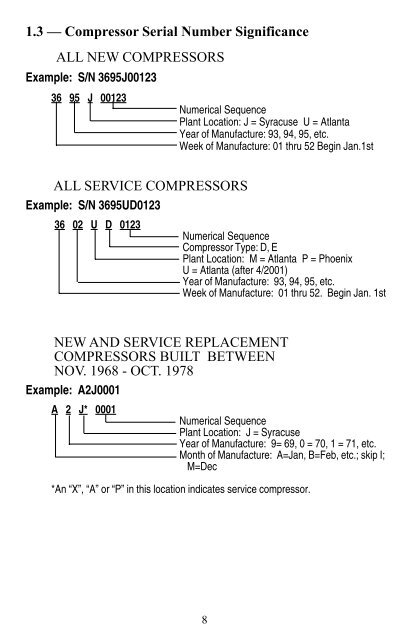
- Page 7: 1.2 — Nameplate SignificanceMODEL
- Page 11 and 12: 1.5 — Service Billing and CreditR
- Page 13 and 14: BEFORE START-UP1. Verify that the c
- Page 15 and 16: compressor unit configurations. Thi
- Page 17 and 18: COMPRESSOR START-UP1. After circuit
- Page 19 and 20: Fig. 1A -- Typical 06D, E Operating
- Page 21 and 22: 2.3 — Troubleshooting Procedures!
- Page 23 and 24: .Troubleshooting Guide - 06D,06E an
- Page 25 and 26: .OBSERVATIONPOSSIBLECAUS EREMED Y6
- Page 27 and 28: 26BSERVATIONO ECAUSOSSIBLEP YREMEDp
- Page 29 and 30: 28BSERVATIONO ECAUSOSSIBLEP YREMEDl
- Page 31 and 32: 30BSERVATIONO ECAUSOSSIBLEP YREMEDt
- Page 33 and 34: 2.4 — Service ProceduresThe servi
- Page 35 and 36: Fig. 2 -- Disassembly of Valve Plat
- Page 37 and 38: REASSEMBLY1. If reassembling existi
- Page 39 and 40: 7. Certain high compression ratio a
- Page 41 and 42: Fig. 7 -- Removing Pump End Bearing
- Page 43 and 44: MOTOR BURNOUT CLEAN-UP PROCEDUREWhe
- Page 45 and 46: 2.5 -- Connection Points, - 06D, 06
- Page 47 and 48: NOTE: Bolt sizes and thread pitch:
- Page 49 and 50: NOTE: Bolt sizes and thread pitch:
- Page 51 and 52: NOTE: Bolt sizes and thread pitch:
- Page 53 and 54: NOTE: Bolt sizes and thread pitch:
- Page 55 and 56: 2.6 -- Cross-Sectional View, 06D Se
- Page 57 and 58: 2.8 -- Exploded View - 6-Cylinder 0
- Page 59 and 60:
2.9 -- Exploded View - 6-Cylinder 0
- Page 61 and 62:
2.10 - Torque Guide - All 06D and 1
- Page 63 and 64:
-------†††††††††
- Page 65 and 66:
------3.2 - 06E Series Compressors
- Page 67 and 68:
3.3 - 06CC Series Compressors - Phy
- Page 69 and 70:
3.4 — 06D, E High Efficiency (H.E
- Page 71 and 72:
FOR HCFC BLENDS:Carlyle’s enginee
- Page 73 and 74:
3.7 — Refrigerants and Oils for 0
- Page 75 and 76:
3.12 — High Flow Oil Pump (Bearin
- Page 77 and 78:
Use of an oil safety switch is reco
- Page 79 and 80:
elow 0°F (-18°C) and all R404A/50
- Page 81 and 82:
LOADED OPERATIONUNLOADED OPERATIONF
- Page 83 and 84:
3.20 — Compressor Mounting DataMo
- Page 85 and 86:
3.27 — Gaskets - Cylinder Head an
- Page 87 and 88:
3.29 — Valve Plate Packages, Serv
- Page 89 and 90:
3.31 — Electrical AccessoriesBOX
- Page 91 and 92:
90* Indicates Vacuum.NOTE: 1 BAR =
- Page 93 and 94:
.4.0 — ELECTRICAL DATA4.1 — 06D
- Page 95 and 96:
944.2 — 06DM, DA 3 Phase Electric
- Page 97 and 98:
4.3 — 06DR, DM Single Phase Elect
- Page 99 and 100:
SEENOTE4RecommendedRLA64.323.933.96
- Page 101 and 102:
SEENOTE4RecommendedRLA64.323.933.96
- Page 103 and 104:
SEENOTE4RecommendedRLA74.327.13574.
- Page 105 and 106:
1044.7 — 06CC (16 to 37 Cfm) 3 Ph
- Page 107 and 108:
1064.8 - 06CC (50 to 99 Cfm) 3 Phas
- Page 109 and 110:
4.9 — 06D Compressor Overloads*(s
- Page 111 and 112:
06E COMPRESSORS(ACROSS-THE-LINE [XL
- Page 113 and 114:
4.11 — Voltage and Current Unbala
- Page 115 and 116:
06D, 06E Compressor Service Workshe
- Page 117 and 118:
Service Guide IndexPage06CC (16 to
- Page 119 and 120:
Current Unbalance .................
- Page 121 and 122:
Parallel Compressor Applications, O
- Page 123 and 124:
Troubleshooting — Low On Capacity