Thermo Scientific Multidrop® 384 - Lab Equipment, Industrial ...
Thermo Scientific Multidrop® 384 - Lab Equipment, Industrial ...
Thermo Scientific Multidrop® 384 - Lab Equipment, Industrial ...

You also want an ePaper? Increase the reach of your titles
YUMPU automatically turns print PDFs into web optimized ePapers that Google loves.
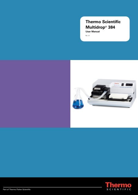
<strong>Thermo</strong> <strong>Scientific</strong><br />
Multidrop ® <strong>384</strong><br />
User Manual<br />
Rev. 3.4
<strong>Thermo</strong> <strong>Scientific</strong><br />
Multidrop ® <strong>384</strong><br />
User Manual<br />
Rev. 3.4, Cat. no. 1507010
CONTENTS<br />
<strong>Thermo</strong> <strong>Scientific</strong> Multidrop <strong>384</strong>, Cat. no. 5840150 or 5840157<br />
User Manual Rev. 3.4; October 2008, Cat. no. 1507010<br />
1 SAFETY SYMBOLS AND MARKINGS........................................................................................... 6<br />
2 ABOUT THE USER MANUAL ........................................................................................................ 7<br />
3 INTRODUCTION TO THE MULTIDROP <strong>384</strong>.................................................................................. 8<br />
4 FUNCTIONAL DESCRIPTION ...................................................................................................... 10<br />
5 INSTALLATION............................................................................................................................. 15<br />
6 ROUTINE OPERATION................................................................................................................. 21<br />
7 MAINTENANCE............................................................................................................................. 36<br />
8 TECHNICAL SPECIFICATIONS ................................................................................................... 60<br />
9 TROUBLESHOOTING................................................................................................................... 66<br />
10 WARRANTY CERTIFICATE ......................................................................................................... 71<br />
11 ORDERING INFORMATION ......................................................................................................... 72<br />
12 GLOSSARY AND ABBREVIATIONS ........................................................................................... 75<br />
13 INDEX............................................................................................................................................. 77<br />
14 TABLE OF FIGURES .................................................................................................................... 81<br />
APPENDIX 1. THERMO SCIENTIFIC MULTIDROP <strong>384</strong> BRIEF USER’S GUIDE.............................. 83<br />
APPENDIX 2. THERMO SCIENTIFIC MULTIDROP <strong>384</strong> FEEDBACK FORM.................................... 84<br />
APPENDIX 3. ADDRESSES................................................................................................................. 85<br />
<strong>Thermo</strong> <strong>Scientific</strong> Multidrop ® <strong>384</strong> User Manual; Rev. 3.4, Cat. no. 1507010 2
TABLE OF CONTENTS<br />
1 SAFETY SYMBOLS AND MARKINGS........................................................................................... 6<br />
2 ABOUT THE USER MANUAL ........................................................................................................ 7<br />
3 INTRODUCTION TO THE MULTIDROP <strong>384</strong>.................................................................................. 8<br />
3.1 INTENDED USE ............................................................................................................................ 8<br />
3.2 PRINCIPLE OF OPERATION............................................................................................................ 8<br />
3.3 ADVANTAGES OF USING THE MULTIDROP <strong>384</strong> ............................................................................... 9<br />
4 FUNCTIONAL DESCRIPTION ...................................................................................................... 10<br />
4.1 INSTRUMENT LAYOUT................................................................................................................. 10<br />
4.1.1 Front view ........................................................................................................................ 10<br />
4.1.2 Back view......................................................................................................................... 13<br />
4.2 MULTIDROP <strong>384</strong> MICROPLATE DISPENSER................................................................................... 14<br />
5 INSTALLATION............................................................................................................................. 15<br />
5.1 INSTALLATION CHECK LIST.......................................................................................................... 15<br />
5.2 WHAT TO DO UPON DELIVERY..................................................................................................... 15<br />
5.2.1 How to unpack................................................................................................................. 15<br />
5.2.2 Checking delivery for completeness................................................................................ 15<br />
5.2.3 Checking for damage during transport............................................................................ 16<br />
5.2.4 Environmental requirements............................................................................................ 16<br />
5.2.5 Things to avoid ................................................................................................................ 16<br />
5.2.6 Technical prerequisites.................................................................................................... 16<br />
5.3 SETUPS BEFORE YOU PUT THE INSTRUMENT INTO OPERATION...................................................... 17<br />
5.3.1 Installation procedure ...................................................................................................... 17<br />
5.3.2 How to ensure startup ..................................................................................................... 18<br />
5.4 OPERATIONAL CHECK ................................................................................................................ 19<br />
5.5 OPERATING PRECAUTIONS AND LIMITATIONS BEFORE OPERATION ................................................ 20<br />
6 ROUTINE OPERATION................................................................................................................. 21<br />
6.1 OPERATIONAL CHECK LIST ......................................................................................................... 21<br />
6.2 SWITCHING ON .......................................................................................................................... 21<br />
6.3 HOW TO INSERT THE PRIMING VESSEL AND THE DISPENSING CASSETTE ........................................ 22<br />
6.4 HOW TO INSERT AND ADJUST THE PLATE ADAPTER ...................................................................... 25<br />
6.5 HOW TO USE THE CONTROL PANEL ............................................................................................. 30<br />
6.5.1 Control panel indicators................................................................................................... 30<br />
6.5.2 Control panel thumbwheels (digital switches) ................................................................. 30<br />
6.5.3 Control panel keys........................................................................................................... 31<br />
6.6 HOW TO SELECT THE 96 / <strong>384</strong>-WELL PLATE................................................................................. 31<br />
6.7 HOW TO PRIME.......................................................................................................................... 32<br />
6.8 DISPENSING.............................................................................................................................. 32<br />
6.8.1 How to dispense automatically........................................................................................ 32<br />
6.8.2 How to dispense manually into the specified column(s) ................................................. 33<br />
6.8.3 How to dispense multiple volumes .................................................................................. 33<br />
6.8.3.1 Dispensing tenfold and hundredfold volumes............................................................................. 33<br />
6.8.4 After use .......................................................................................................................... 34<br />
6.9 SHUTDOWN............................................................................................................................... 35<br />
6.10 GUIDELINES FOR USE............................................................................................................. 35<br />
7 MAINTENANCE............................................................................................................................. 36<br />
7.1 REGULAR AND PREVENTIVE MAINTENANCE.................................................................................. 36<br />
7.1.1 General ............................................................................................................................ 36<br />
7.1.2 Immediate ........................................................................................................................ 36<br />
7.2 HOW TO WASH THE DISPENSING CASSETTE................................................................................. 37<br />
7.3 HOW TO AUTOCLAVE THE DISPENSING CASSETTE ........................................................................ 37<br />
<strong>Thermo</strong> <strong>Scientific</strong> Multidrop ® <strong>384</strong> User Manual; Rev. 3.4, Cat. no. 1507010 3
7.4 HOW TO REPLACE THE FUSES .................................................................................................... 38<br />
7.5 HOW TO RECALIBRATE THE DISPENSING CASSETTE...................................................................... 40<br />
7.5.1 Volumetric calibration ...................................................................................................... 40<br />
7.5.2 Gravimetric calibration..................................................................................................... 42<br />
7.6 HOW TO CHANGE THE TUBING SET.............................................................................................. 45<br />
7.6.1 Changing the tip band ..................................................................................................... 45<br />
7.6.2 Fitting the new tubing set step by step ............................................................................ 46<br />
7.7 DISPOSAL OF MATERIALS ........................................................................................................... 57<br />
7.8 DECONTAMINATION PROCEDURE ................................................................................................ 57<br />
7.9 HOW TO PACK FOR SERVICE....................................................................................................... 58<br />
7.10 SERVICE CONTRACTS............................................................................................................. 58<br />
7.11 DISPOSAL OF THE INSTRUMENT .............................................................................................. 58<br />
8 TECHNICAL SPECIFICATIONS ................................................................................................... 60<br />
8.1 GENERAL SPECIFICATIONS......................................................................................................... 60<br />
8.2 SAFETY SPECIFICATIONS............................................................................................................ 61<br />
8.2.1 Live parts ......................................................................................................................... 61<br />
8.3 IN CONFORMITY WITH THE REQUIREMENTS .................................................................................. 62<br />
8.4 REMOTE CONTROL TO MULTIDROP <strong>384</strong> ...................................................................................... 63<br />
8.4.1 Hardware for the computer port ...................................................................................... 63<br />
8.4.2 Multidrop <strong>384</strong> PC interface .............................................................................................. 63<br />
9 TROUBLESHOOTING................................................................................................................... 66<br />
9.1 TROUBLESHOOTING GUIDE......................................................................................................... 66<br />
9.2 FAQS ABOUT THE MULTIDROP <strong>384</strong> ............................................................................................ 67<br />
9.3 HAZARDS.................................................................................................................................. 68<br />
9.3.1 Electrical .......................................................................................................................... 68<br />
9.3.2 Mechanical....................................................................................................................... 68<br />
9.3.3 Environmental.................................................................................................................. 68<br />
9.3.4 Defects and abnormal stresses....................................................................................... 69<br />
9.4 SERVICE REQUEST PROTOCOL ................................................................................................... 69<br />
9.4.1 Decontamination.............................................................................................................. 69<br />
9.4.1.1 Certificate of Decontamination ................................................................................................... 70<br />
10 WARRANTY CERTIFICATE...................................................................................................... 71<br />
10.1 WARRANTY CERTIFICATE ....................................................................................................... 71<br />
11 ORDERING INFORMATION...................................................................................................... 72<br />
11.1 INSTRUMENTS ....................................................................................................................... 72<br />
11.2 DISPENSING CASSETTES ........................................................................................................ 72<br />
11.3 SPARE PARTS FOR DISPENSING CASSETTES ............................................................................ 73<br />
11.4 PRIMING VESSELS (CONSUMABLES) ........................................................................................ 73<br />
11.5 LIST OF ACCESSORIES............................................................................................................ 73<br />
11.6 LIST OF PLATES (CONSUMABLES)............................................................................................ 73<br />
11.7 LIST OF SPARE PARTS ............................................................................................................ 74<br />
11.8 LIST OF RECOMMENDED SPARE PARTS .................................................................................... 74<br />
12 GLOSSARY AND ABBREVIATIONS ....................................................................................... 75<br />
12.1 KEYWORDS FOR WEB PAGES .................................................................................................. 76<br />
12.2 LITERATURE .......................................................................................................................... 76<br />
13 INDEX......................................................................................................................................... 77<br />
14 TABLE OF FIGURES................................................................................................................. 81<br />
APPENDIX 1. THERMO SCIENTIFIC MULTIDROP <strong>384</strong> BRIEF USER’S GUIDE.............................. 83<br />
APPENDIX 2. THERMO SCIENTIFIC MULTIDROP <strong>384</strong> FEEDBACK FORM.................................... 84<br />
APPENDIX 3. ADDRESSES................................................................................................................. 85<br />
<strong>Thermo</strong> <strong>Scientific</strong> Multidrop ® <strong>384</strong> User Manual; Rev. 3.4, Cat. no. 1507010 4
Copyright<br />
Copyright © 2008 <strong>Thermo</strong> Fisher <strong>Scientific</strong> Corporation. All rights reserved. First edition published in<br />
1987. Printed in Finland. Reproduction of the accompanying user documentation in whole or in part is<br />
prohibited.<br />
Patents<br />
This product is protected by the following patent: US 4995432.<br />
Trademarks<br />
Immulon, Microfluor and Multidrop are registered trademarks of <strong>Thermo</strong> Fisher <strong>Scientific</strong>.<br />
Microlite is a trademark of <strong>Thermo</strong> Fisher <strong>Scientific</strong>.<br />
All other trademarks and registered trademarks are the property of their respective holders.<br />
Disclaimer<br />
<strong>Thermo</strong> Fisher <strong>Scientific</strong> reserves the right to change its products and services at any time to<br />
incorporate technological developments. This manual is subject to change without prior notice as part<br />
of a continuous product development.<br />
Although this manual has been prepared with every precaution to ensure accuracy, <strong>Thermo</strong> Fisher<br />
<strong>Scientific</strong> assumes no liability for any errors or omissions, nor for any damages resulting from the<br />
application or use of this information. This manual supersedes all previous editions.<br />
No liability for consequential damages<br />
<strong>Thermo</strong> Fisher <strong>Scientific</strong> shall not be liable for any damages whatsoever arising out of the use or<br />
inability to use this product.<br />
Contact information<br />
<strong>Thermo</strong> Fisher <strong>Scientific</strong> Oy<br />
P.O. Box 100, FI-01621 Vantaa, Finland<br />
Tel. +358-9-329 100, Fax +358-9-3291 0415<br />
www.thermo.com<br />
<strong>Thermo</strong> <strong>Scientific</strong> Multidrop ® <strong>384</strong> User Manual; Rev. 3.4, Cat. no. 1507010 5
1 SAFETY SYMBOLS AND MARKINGS<br />
Chapter 1: Safety Symbols and Markings<br />
These symbols are intended to draw your attention to essential information and alert you to the<br />
presence of hazards as indicated.<br />
SAFETY SYMBOLS USED IN THE MULTIDROP <strong>384</strong><br />
Power ON<br />
Power OFF<br />
WEEE symbol This product is required to comply with the European<br />
Union’s Waste Electrical & Electronic <strong>Equipment</strong><br />
(WEEE) Directive 2002/96/EC.<br />
WARNING MARKINGS USED IN THE DOCUMENTATION<br />
Caution: risk of electric shock.<br />
Caution: biohazard risk.<br />
Caution: risk of personal injury to the operator or a safety hazard to the<br />
surrounding area.<br />
Caution: risk of damage to the instrument, other equipment or loss of<br />
performance or function in a specific application.<br />
<strong>Thermo</strong> <strong>Scientific</strong> Multidrop ® <strong>384</strong> User Manual; Rev. 3.4, Cat. no. 1507010 6
2 ABOUT THE USER MANUAL<br />
Chapter 2: About the User Manual<br />
This user manual has been written for the end user (for example, laboratory technician) and provides<br />
information on the <strong>Thermo</strong> <strong>Scientific</strong> Multidrop <strong>384</strong> microplate dispenser. This manual contains the<br />
installation and operating instructions for the Multidrop <strong>384</strong> microplate dispenser.<br />
Read the manual in its entirety prior to operating the instrument.<br />
This user manual has been designed to give you the information you need to:<br />
• Review safety precautions<br />
• Install the Multidrop <strong>384</strong><br />
• Carry out dispensing procedures<br />
• Recalibrate the dispensing cassette<br />
• Perform basic maintenance procedures<br />
• Troubleshoot the instrument performance<br />
This user manual also describes features and specifications of the Multidrop <strong>384</strong> hardware and<br />
onboard software.<br />
Chapter 6 ROUTINE OPERATION explains the dispensing principles and procedures.<br />
In Chapter 9 TROUBLESHOOTING you will find a problem-solving guide. The user should be familiar<br />
with the contents of Chapter 7 on maintenance.<br />
For warranty and ordering information refer to Chapters 10 WARRANTY CERTIFICATE and 11<br />
ORDERING INFORMATION.<br />
In an effort to produce useful and appropriate documentation, we appreciate your comments on this<br />
document to your local <strong>Thermo</strong> Fisher <strong>Scientific</strong> representative.<br />
<strong>Thermo</strong> <strong>Scientific</strong> Multidrop ® <strong>384</strong> User Manual; Rev. 3.4, Cat. no. 1507010 7
3 INTRODUCTION TO THE MULTIDROP <strong>384</strong><br />
There are two models of the Multidrop <strong>384</strong>:<br />
• 5840150 Multidrop <strong>384</strong>, 220―240 V 50/60 Hz<br />
• 5840157 Multidrop <strong>384</strong>, 110―120 V 50/60 Hz<br />
Each Multidrop <strong>384</strong> comes with one dispensing cassette:<br />
• 24072670 Standard tube dispensing cassette (with 40 cm tubing set)<br />
3.1 Intended use<br />
Chapter 3: Introduction to the Multidrop <strong>384</strong><br />
The Multidrop <strong>384</strong> microplate dispenser is intended for professional research use by trained<br />
personnel. The instrument is intended for automated dispensing of up to eight different reagents<br />
simultaneously into microplates and strips in 96 or <strong>384</strong>-well plate format. Use for self-testing is<br />
excluded.<br />
3.2 Principle of operation<br />
The Multidrop <strong>384</strong> is an automatic, programmable, eight-channel microplate dispenser. It has a<br />
peristaltic pump for rapid and continuous dispensing of liquids into 96 and <strong>384</strong>-well microplates. It can<br />
dispense 1 to 8 different reagents from external liquid reservoirs into different rows and can be used in<br />
most microtitration techniques, for example, in the fields of bacteriology, cell biology, hematology,<br />
immunology, toxicology and virology. It is particularly useful in the pharmaceutical industry. The<br />
Multidrop <strong>384</strong> is lightweight, transportable and compact on a laboratory bench. It can dispense 20 µl<br />
into the entire <strong>384</strong>-well microplate in 20 seconds or 20 µl into the entire 96-well microplate in<br />
5 seconds.<br />
Fig. 3.1 Multidrop <strong>384</strong> microplate dispenser<br />
<strong>Thermo</strong> <strong>Scientific</strong> Multidrop ® <strong>384</strong> User Manual; Rev. 3.4, Cat. no. 1507010 8
3.3 Advantages of using the Multidrop <strong>384</strong><br />
Chapter 3: Introduction to the Multidrop <strong>384</strong><br />
The Multidrop <strong>384</strong> microplate dispenser provides several advantages relating mainly to the principle of<br />
operation in that it has:<br />
• Superior accuracy and precision<br />
• A flexible volume range<br />
• High-speed continuous dispensing<br />
• Robot compatibility and versatile remote control commands<br />
• An autoclavable, detachable and calibrateable dispensing cassette<br />
The Multidrop <strong>384</strong> is an automated microplate dispenser designed for high-throughput screening and<br />
microvolume dispensing into <strong>384</strong> and 96-well plates.<br />
The Multidrop <strong>384</strong> can dispense up to eight different reagents with high accuracy, precision and<br />
speed. It fills a <strong>384</strong>-well plate with 20 µl/well in 20 seconds or a 96-well plate in 5 seconds. With a<br />
volume range of 5 ― 100 µl for <strong>384</strong>-well plates and 5 ― 395 µl for 96-well plates, the Multidrop <strong>384</strong><br />
offers superior flexibility for a wide range of applications.<br />
All reagent lines can be backflushed to the reagent bottle, minimizing the loss of expensive reagents.<br />
From 1 to 24 columns can be selected for <strong>384</strong>-well plates and from 1 to 12 columns for 96-well plates.<br />
To ensure sterility and avoid cross contamination, the dispensing cassette is detachable and<br />
autoclavable.<br />
The Multidrop <strong>384</strong> can be used as a standalone instrument or added to robotic systems via an RS-232<br />
serial port.<br />
<strong>Thermo</strong> <strong>Scientific</strong> Multidrop ® <strong>384</strong> User Manual; Rev. 3.4, Cat. no. 1507010 9
4 FUNCTIONAL DESCRIPTION<br />
4.1 Instrument layout<br />
4.1.1 Front view<br />
14<br />
13<br />
15<br />
12 11<br />
16<br />
8<br />
7<br />
1 Instrument cover<br />
2 Control panel<br />
3 Thumbwheels for selecting the volume (volume µl) and number of columns (col)<br />
4 Plate switch (plate) for selecting the 96/<strong>384</strong>-well plate (= rocker switch)<br />
5 Plate carrier<br />
6 Plate adapter<br />
7 Plate adapter lock<br />
8 Transfer rails<br />
9 Priming vessel<br />
10 Lower part slots<br />
11 Upper part slots<br />
12 Rest position slots of the upper part<br />
13 Pump rotor<br />
14 Rotor needles<br />
15 Rotor cover not pulled over the rotor<br />
16 Pump body<br />
10<br />
9<br />
6<br />
Fig. 4.1 Multidrop <strong>384</strong> front view (A)<br />
Chapter 4: Functional Description<br />
<strong>Thermo</strong> <strong>Scientific</strong> Multidrop ® <strong>384</strong> User Manual; Rev. 3.4, Cat. no. 1507010 10<br />
4<br />
3<br />
5<br />
1<br />
2
1<br />
2<br />
3<br />
1 Mains switch (ON/OFF)<br />
2 Instrument cover retaining screws<br />
3 Cooling-air outlet<br />
Fig. 4.2 Multidrop <strong>384</strong> front view (B)<br />
1<br />
1 Rotor cover pulled over the rotor<br />
2 Standard tube dispensing cassette attached<br />
3 Plate adapter<br />
4 Plate carrier<br />
Fig. 4.3 Multidrop <strong>384</strong> front view (C)<br />
Chapter 4: Functional Description<br />
<strong>Thermo</strong> <strong>Scientific</strong> Multidrop ® <strong>384</strong> User Manual; Rev. 3.4, Cat. no. 1507010 11<br />
2<br />
3<br />
2<br />
4
2<br />
1<br />
3<br />
Chapter 4: Functional Description<br />
1 Tips (8)<br />
2 Lower part of dispensing cassette with tips<br />
3 Tension limiting wires (2)<br />
4 Upper part of dispensing cassette with tubes<br />
5 Sight strips (8)<br />
6 Tubes (A ― H)<br />
7 Tubing weight, eight tubes<br />
8 Calibration screw cover<br />
Fig. 4.4 Close-up of the Multidrop <strong>384</strong> standard tube dispensing cassette<br />
<strong>Thermo</strong> <strong>Scientific</strong> Multidrop ® <strong>384</strong> User Manual; Rev. 3.4, Cat. no. 1507010 12<br />
4<br />
5<br />
8<br />
6<br />
7
4.1.2 Back view<br />
1 Mains input socket<br />
2 Fuses in the fuse holder cap<br />
3 RS-232C serial interface connector<br />
3<br />
Fig. 4.5 Multidrop <strong>384</strong> rear view<br />
Chapter 4: Functional Description<br />
<strong>Thermo</strong> <strong>Scientific</strong> Multidrop ® <strong>384</strong> User Manual; Rev. 3.4, Cat. no. 1507010 13<br />
2<br />
1
4.2 Multidrop <strong>384</strong> microplate dispenser<br />
Chapter 4: Functional Description<br />
The Multidrop <strong>384</strong> microplate dispenser (Fig. 4.6) automates dispensing into microplates. The<br />
microprocessor-based system permits volumes between 5 ― 100 µl for <strong>384</strong>-well plates and 5 ― 395 µl<br />
for 96-well plates to be selected (in 5 µl increments) and then dispensed simultaneously into eight<br />
wells (one column of a 96-well microplate). Setting the volume to be dispensed and the number of<br />
columns per plate (maximum 12 columns in 96-well plates and 24 columns in <strong>384</strong>-well plates) is<br />
carried out using thumbwheels.<br />
The movement of the microplate is automatic:<br />
In the 96-well plate mode, the columns with 8 wells are filled starting from column 1 up to the column<br />
number set, after which the plate carrier will return to the home position. In the <strong>384</strong>-well plate mode,<br />
the columns with 16 wells must be filled in two phases: first every other row (A, C, ..., M, O) is filled<br />
starting from column 1 up to the set column number. Then the plate carrier shifts sideways so that the<br />
remaining rows (B, D, ..., N, P) are filled in the opposite order, from the set column number back to<br />
column 1.<br />
Normally, the microplate moves through the instrument automatically, but a semiautomatic mode is<br />
possible by using the step and drop keys, which control dispensing into any column of the plate.<br />
The dispensing cassette contains eight individual tubes. The dispensing cassette is detachable. Each<br />
reagent can have a separate dispensing cassette. Alternatively, the same dispensing cassette can be<br />
used with several reagents using the backflush feature. Refer to section 11.2 Dispensing cassettes.<br />
The latest technology has been used in the manufacture of the dispensing cassette which includes an<br />
injection molded manifold. All dispensing cassettes can be autoclaved and <strong>Thermo</strong> Fisher <strong>Scientific</strong><br />
guarantees them up to 50 autoclavings. After this amount it is recommended you replace the cassette.<br />
To avoid damaging the tubes, follow the dispensing cassette maintenance, washing, autoclaving and<br />
storage instructions carefully (see the instructions in sections 6.8.4 After use, 7.2 How to wash the<br />
dispensing cassette and 7.3 How to autoclave the dispensing cassette).<br />
Fig. 4.6 Multidrop <strong>384</strong> microplate dispenser<br />
<strong>Thermo</strong> <strong>Scientific</strong> Multidrop ® <strong>384</strong> User Manual; Rev. 3.4, Cat. no. 1507010 14
5 INSTALLATION<br />
5.1 Installation check list<br />
Chapter 5: Installation<br />
The chapter on installation will contain an outline of the points mentioned in the check list below.<br />
Tick Item<br />
�<br />
�<br />
�<br />
�<br />
�<br />
�<br />
�<br />
Unpack the Multidrop <strong>384</strong> instrument carefully. Refer to 5.2.1. Keep the original packaging<br />
and packing material for future transportation.<br />
Check the delivery for completeness. Refer to 5.2.2.<br />
Check for damage during transport. Refer to 5.2.3.<br />
Place the dispenser on a normal laboratory bench taking into account both the environmental<br />
and technical prerequisites. Refer to 5.2.4 and 5.2.6. Leave sufficient clearance on both sides<br />
and at the rear of the unit.<br />
Install the instrument. Refer to 5.3.1.<br />
Connect the mains supply cable to the mains input socket. See 5.3.2.<br />
Carry out the operational check. Refer to 5.4.<br />
5.2 What to do upon delivery<br />
5.2.1 How to unpack<br />
Move the unpacked instrument to its site of operation. Unpack the Multidrop <strong>384</strong> instrument and<br />
accessories carefully with the arrows on the transport package pointing upwards. The following notes<br />
and instructions are sent with the instrument and are immediately available when you open the<br />
package:<br />
• Warranty Certificate card<br />
• packing instructions/packing list<br />
• Multidrop <strong>384</strong> User Manual<br />
Caution: Do not touch or loosen any screws or parts other than those specially<br />
designated in the instructions. Doing so might cause misalignment and will invalidate the<br />
instrument warranty.<br />
Retain the original packaging and packing material for future transportation. The packaging is<br />
designed to assure safe transport and minimize transit damage. Use of alternative packaging<br />
materials may invalidate the warranty. Also retain all instrument-related documentation provided by<br />
the manufacturer for future use.<br />
5.2.2 Checking delivery for completeness<br />
Check the enclosed packing list against order. If any parts are missing, contact <strong>Thermo</strong> Fisher<br />
<strong>Scientific</strong> Oy or your local <strong>Thermo</strong> Fisher <strong>Scientific</strong> representative.<br />
<strong>Thermo</strong> <strong>Scientific</strong> Multidrop ® <strong>384</strong> User Manual; Rev. 3.4, Cat. no. 1507010 15
5.2.3 Checking for damage during transport<br />
Chapter 5: Installation<br />
Visually inspect the transport package, the instrument and the accessories for any possible transport<br />
damage.<br />
If the carton has been damaged in transit, it is particularly important that you retain it for inspection by<br />
the carrier in case there has also been damage to the instrument.<br />
Neither the manufacturer nor its agents can be held responsible for any damage incurred in transit,<br />
but the manufacturer will make every effort to help obtain restitution from the carrier. Upon receipt of<br />
the carrier's inspection report, arrangements will be made for repair or replacement.<br />
Visually check all interconnections in the basic instrument. Check that there are no loose parts inside<br />
the instrument.<br />
If any parts are damaged, contact <strong>Thermo</strong> Fisher <strong>Scientific</strong> Oy or your local <strong>Thermo</strong> Fisher <strong>Scientific</strong><br />
representative.<br />
5.2.4 Environmental requirements<br />
When you set up your Multidrop <strong>384</strong>, avoid sites of operation with excess dust, vibrations, strong<br />
magnetic fields, direct sunlight, draft, excessive moisture or large temperature fluctuations.<br />
• Make sure the working area is flat, dry, clean and vibration-proof and leave additional room for<br />
accessories, cables, reagent bottles, etc.<br />
• Make sure the ambient air is clean and free of corrosive vapors, smoke and dust.<br />
• Make sure the ambient temperature range is between +10°C (50°F) and +40°C (104°F).<br />
• Make sure relative humidity is between 10% and 80% (non-condensing).<br />
Leave sufficient space (at least 10 cm) on both sides and at the back of the unit to allow adequate air<br />
circulation.<br />
The Multidrop <strong>384</strong> does not produce operating noise at a level that would be harmful. No sound level<br />
measurements are required after installation.<br />
Warning: Do not operate the instrument in an environment where potentially damaging<br />
liquids or gases are present.<br />
5.2.5 Things to avoid<br />
Do not smoke, eat or drink while using the Multidrop <strong>384</strong>. Wash your hands thoroughly after handling<br />
test fluids. Observe normal laboratory procedures for handling potentially dangerous samples. Use<br />
proper protective clothing. Use disposable gloves. Be sure the working area is well-ventilated.<br />
Never spill fluids in or on the equipment.<br />
5.2.6 Technical prerequisites<br />
Place the instrument on a normal laboratory bench. The net weight of the entire equipment is approx.<br />
6.2 kg [13.7 lbs.] and the dispensing cassette 124 g [0.3 lb.].<br />
The instrument operates at voltages of 100 – 240 Vac and a frequency range of 50 – 60 Hz.<br />
<strong>Thermo</strong> <strong>Scientific</strong> Multidrop ® <strong>384</strong> User Manual; Rev. 3.4, Cat. no. 1507010 16
5.3 Setups before you put the instrument into operation<br />
5.3.1 Installation procedure<br />
Chapter 5: Installation<br />
The following procedure may be carried out by any properly skilled person using standard tools. In<br />
case the local voltage does not correspond to the label at the rear of the instrument on top of the<br />
mains input socket (Fig. 4.5), follow the next installation procedures.<br />
Warning: Ensure the mains switch (Fig. 4.2) on the rear of the left side panel is in the<br />
OFF position. Also ensure the mains supply cable is disconnected (Fig. 5.3).<br />
1. Remove the instrument cover retaining screws (Fig. 5.1 and Fig. 4.2) and lift up the cover.<br />
Cover retaining screw on both sides<br />
Fig. 5.1 Location of the cover retaining screws<br />
2. Check that the voltage selector switch (Fig. 5.2) is in the correct position, that is, the voltage<br />
selected corresponds to the local voltage.<br />
Voltage<br />
Fig. 5.2 Location of the voltage selector<br />
<strong>Thermo</strong> <strong>Scientific</strong> Multidrop ® <strong>384</strong> User Manual; Rev. 3.4, Cat. no. 1507010 17
3. Visually check that you did not leave any loose parts inside the instrument.<br />
4. Close the cover and fasten the cover retaining screws.<br />
5.3.2 How to ensure startup<br />
Chapter 5: Installation<br />
1. Warning: Ensure the mains switch (Fig. 4.2) on the rear of the left side panel is in the<br />
OFF position.<br />
2. Connect the mains supply cable to the mains input socket (Fig. 4.3 and Fig. 5.3) at the<br />
bottom of the back panel. If you need to use any other type of mains supply cable than<br />
supplied, use only cables certified by the local authorities.<br />
3. Connect the instrument to a correctly installed line power outlet that has a protective<br />
conductor that is grounded.<br />
Warning: Never operate your instrument from a power outlet that has no ground<br />
connection. Never use a mains supply cable other than the <strong>Thermo</strong> <strong>Scientific</strong> mains<br />
supply cable designed for your region.<br />
Fig. 5.3 Connecting the mains supply cable<br />
<strong>Thermo</strong> <strong>Scientific</strong> Multidrop ® <strong>384</strong> User Manual; Rev. 3.4, Cat. no. 1507010 18
1<br />
2<br />
3<br />
4<br />
5<br />
6<br />
7<br />
8<br />
5.4 Operational check<br />
Chapter 5: Installation<br />
The following procedure should be completed without the dispensing cassette to confirm the correct<br />
functioning of the dispenser prior to normal use.<br />
Connect the mains supply cable (Fig. 5.3).<br />
Switch the instrument on using the mains switch (Fig. 4.2).<br />
• If the instrument starts:<br />
- The green power LED will light up<br />
- The plate carrier will return to the home position<br />
• If the instrument does not start:<br />
�Pull the rotor cover over the rotor<br />
�Check the mains cable connection<br />
Press prime/drop to prime<br />
- The pump rotor will rotate<br />
• If the pump rotor does not rotate:<br />
�Pull the rotor cover over the rotor<br />
• If the red error LED lights up:<br />
�Insert the priming vessel, press the stop key and prime again<br />
Press start<br />
- Starts the dispensing cycle<br />
• If the dispensing cycle does not start:<br />
�Pull the rotor cover over the rotor<br />
• If the red error LED lights up:<br />
�Press the stop key, then press the prime key and finally press the start key again<br />
�Insert the priming vessel, press the stop key, then press the prime key and finally press the<br />
start key again<br />
plate (plate switch)<br />
- Dispenses liquid into the <strong>384</strong> or 96-well microplates<br />
- Try the alternative plate formats by pressing the start key<br />
step - Advances the microplate by one column<br />
• If the microplate does not advance:<br />
�Pull the rotor cover over the rotor<br />
After step press prime/drop<br />
- To dispense a preselected volume into the column selected by steps<br />
- The plate carrier will return to the home position after reaching the last column<br />
After step press start (partial filling of the tubing)<br />
- To dispense the selected volume automatically from the set column to the last column<br />
empty - The pump rotor will rotate<br />
• If the pump rotor does not rotate:<br />
�Pull the rotor cover over the rotor<br />
stop<br />
- Terminates the operation and returns the plate to the home position<br />
For more information on the control panel, refer to section 6.5 How to use the control panel.<br />
<strong>Thermo</strong> <strong>Scientific</strong> Multidrop ® <strong>384</strong> User Manual; Rev. 3.4, Cat. no. 1507010 19
5.5 Operating precautions and limitations before operation<br />
Chapter 5: Installation<br />
1. Read this manual in its entirety, as it contains information necessary to ensure safe operation.<br />
2. Always ensure that the local supply voltage in the laboratory conforms to that specified on the type<br />
label on the back of the instrument.<br />
<strong>Thermo</strong> <strong>Scientific</strong> Multidrop ® <strong>384</strong> User Manual; Rev. 3.4, Cat. no. 1507010 20
6 ROUTINE OPERATION<br />
6.1 Operational check list<br />
Chapter 6: Routine Operation<br />
The chapter on routine operation will contain an outline of the points mentioned in the check list below.<br />
Tick Item<br />
�<br />
�<br />
�<br />
�<br />
�<br />
Switch on the instrument. Refer to 6.2.<br />
Insert the priming vessel and the dispensing cassette. Refer to 6.3.<br />
Use the plate adapter for the plate carrier to function. Refer to 6.4.<br />
Pull the rotor cover over the rotor. Refer to 6.3.<br />
Familiarize yourself with the control panel. Refer to 6.5.<br />
� Press the plate switch (plate) to position 96 or <strong>384</strong> according to the plate type you use.<br />
Refer to 6.5.2.<br />
�<br />
�<br />
Prime all the eight channels so that there are no air bubbles in the tubes. Refer to 6.7.<br />
Carry out dispensing either manually or automatically. Refer to 6.8.<br />
� After all the plates have been dispensed, press the empty key to return the reagent or liquid<br />
from the tubes to the reservoir. Refer to 6.8.4.<br />
�<br />
�<br />
�<br />
Wash the dispensing cassette by priming it with deionized distilled water when not in use.<br />
Refer to 6.8.4 and 7.2.<br />
After washing, store the dispensing cassette in the rest position. Refer to 6.8.4 and 7.2.<br />
Maintain the instrument regularly. Refer to Chapter 7.<br />
Note: Keep the dispensing cassette in the rest position when the dispensing cassette is<br />
not in use.<br />
6.2 Switching on<br />
Switch on the instrument by using the mains switch on the left-hand side of the instrument (Fig. 4.2).<br />
The green power LED will light up.<br />
<strong>Thermo</strong> <strong>Scientific</strong> Multidrop ® <strong>384</strong> User Manual; Rev. 3.4, Cat. no. 1507010 21
6.3 How to insert the priming vessel and the dispensing cassette<br />
Chapter 6: Routine Operation<br />
1. Ensure that the priming vessel is inserted correctly into its slot on the left of the plate carrier<br />
(Fig. 6.1). You have fastened it correctly when it snaps slightly and is inserted into the sensor<br />
slot.<br />
Priming vessel<br />
sensor slot<br />
Fig. 6.1 Inserting the priming vessel into place<br />
2. Take the lower part of the cassette into your right hand with the dispensing tips pointing down<br />
and the upper part into your left hand (Fig. 6.2).<br />
Fig. 6.2 Inserting the standard tube dispensing cassette<br />
<strong>Thermo</strong> <strong>Scientific</strong> Multidrop ® <strong>384</strong> User Manual; Rev. 3.4, Cat. no. 1507010 22
Chapter 6: Routine Operation<br />
3. Carefully place the eight tubes below the pump rotor and insert the lower part of the cassette into<br />
the lower part slots of the pump body (Fig. 6.3). Check that the tubes are freely placed below the<br />
rotor and the tension limiting wires below the rotor shaft.<br />
Lower part slots<br />
Fig. 6.3 Inserting the lower part of the dispensing cassette into its slots<br />
4. Take a firm grip on the upper part of the cassette with your right hand and carefully pull the tubes<br />
around the rotor until the upper part reaches and fits into the upper part slots of the pump body<br />
(Fig. 6.4 and Fig. 4.1).<br />
Fig. 6.4 Inserting the upper part of the dispensing cassette<br />
<strong>Thermo</strong> <strong>Scientific</strong> Multidrop ® <strong>384</strong> User Manual; Rev. 3.4, Cat. no. 1507010 23
Chapter 6: Routine Operation<br />
Note: The tension limiting wires are designed to prevent the user from pulling the tubes<br />
too much as excessive tension may damage the tubes or change the calibration of the<br />
cassette.<br />
5. Double-check that both the upper and the lower parts are properly placed into their<br />
corresponding slots (Fig. 6.3 and Fig. 6.5).<br />
Upper part slots<br />
Fig. 6.5 Lower and upper parts of the dispensing cassette inserted evenly into their slots<br />
6. Ensure that all the tubes are evenly placed on the rotor needles, four tubes on each half of the<br />
rotor.<br />
7. Ensure also that the tension limiting wires have a loose fit around the rotor shaft.<br />
8. PULL THE ROTOR COVER OVER THE ROTOR (Fig. 6.6). The plate carrier will then return to<br />
the furthest right of the instrument, that is, the home position. The microswitch controls that the<br />
cover is properly placed over the rotor. The Multidrop <strong>384</strong> is now ready for priming.<br />
Fig. 6.6 Pulling the rotor cover over the rotor<br />
<strong>Thermo</strong> <strong>Scientific</strong> Multidrop ® <strong>384</strong> User Manual; Rev. 3.4, Cat. no. 1507010 24
Chapter 6: Routine Operation<br />
Note: If the rotor cover is not pulled over the rotor, the instrument will not function.<br />
Note: It is recommended you change the dispensing cassette or tubing set after<br />
dispensing about 3000 – 5000 96-well plates, depending on the dispensing frequency and<br />
the liquids used.<br />
Note: Keep the dispensing cassette in the rest position when the dispensing cassette is<br />
not in use.<br />
6.4 How to insert and adjust the plate adapter<br />
The Multidrop <strong>384</strong> requires a plate adapter for the plate carrier to function. Two different plate<br />
adapters are included (Fig. 6.7).<br />
Fig. 6.7 Two different plate adapters<br />
The PLATE ADAPTER, PLATE<br />
HEIGHT MAX. 15 MM, is<br />
suitable for plates approximately<br />
15 mm high, for example, 96well<br />
plates and some <strong>384</strong>-well<br />
plates.<br />
The PLATE ADAPTER, PLATE<br />
HEIGHT MAX. 11 MM, is<br />
suitable for lower plates, for<br />
example, <strong>384</strong>-well plates.<br />
<strong>Thermo</strong> <strong>Scientific</strong> Multidrop ® <strong>384</strong> User Manual; Rev. 3.4, Cat. no. 1507010 25
The plate adapter is inserted into the plate carrier in the following way:<br />
Chapter 6: Routine Operation<br />
1. Open the plate adapter lock located in the front left corner of the plate carrier (Fig. 6.8). Select<br />
the plate adapter according to the height of the plate.<br />
Fig. 6.8 Opening the plate adapter lock<br />
2. Take the plate adapter in your left hand and lower the right end. Place the plate adapter into the<br />
right end corner of the plate carrier (Fig. 6.9).<br />
Plate adapter lock<br />
Fig. 6.9 Placing the right end of the plate adapter<br />
<strong>Thermo</strong> <strong>Scientific</strong> Multidrop ® <strong>384</strong> User Manual; Rev. 3.4, Cat. no. 1507010 26
3. Then press the left end of the plate adapter onto the plate carrier (Fig. 6.10).<br />
Fig. 6.10 Pressing the left end of the plate adapter<br />
Chapter 6: Routine Operation<br />
4. Lock the plate adapter into place with the plate adapter lock located in the front left corner of the<br />
plate carrier (Fig. 6.11).<br />
Fig. 6.11 Closing the plate adapter lock<br />
<strong>Thermo</strong> <strong>Scientific</strong> Multidrop ® <strong>384</strong> User Manual; Rev. 3.4, Cat. no. 1507010 27
Chapter 6: Routine Operation<br />
5. To adjust the plate size, loosen first the two attached plastic-covered screws on the right of the<br />
plate carrier (Fig. 6.12).<br />
Fig. 6.12 Loosening the screws on the right of the plate carrier<br />
6. Then loosen the two attached plastic-covered screws at the front of the plate adapter (Fig. 6.13).<br />
Fig. 6.13 Loosening the screws at the front of the plate adapter<br />
<strong>Thermo</strong> <strong>Scientific</strong> Multidrop ® <strong>384</strong> User Manual; Rev. 3.4, Cat. no. 1507010 28
Chapter 6: Routine Operation<br />
7. Insert the microplate onto the plate adapter. Push the microplate at the same time towards the<br />
left-hand top corner of the plate adapter while you fasten the front screws (Fig. 6.14).<br />
Fig. 6.14 Fastening the front screws of the plate adapter<br />
8. Then fasten the screws to the right of the plate carrier, pushing the microplate simultaneously<br />
towards the left-hand corner of the plate adapter (Fig. 6.15). If the instrument is used for robotics,<br />
leave sufficient moving space for the microplate according to the robotic specifications.<br />
Fig. 6.15 Fastening the screws to the right of the plate carrier<br />
Note: Ensure the dispensing cassette is attached and the rotor cover has been pulled<br />
over the rotor.<br />
<strong>Thermo</strong> <strong>Scientific</strong> Multidrop ® <strong>384</strong> User Manual; Rev. 3.4, Cat. no. 1507010 29
6.5 How to use the control panel<br />
Chapter 6: Routine Operation<br />
The keypad has an embossed, tactile membrane with five keys. There are two control panel indicators<br />
(LEDs) in all.<br />
The control panel is shown in Fig. 6.16.<br />
6.5.1 Control panel indicators<br />
power<br />
Fig. 6.16 Multidrop <strong>384</strong> control panel<br />
The green power LED indicates that the dispenser is powered.<br />
error The red error LED shows when the dispenser has some kind of error.<br />
6.5.2 Control panel thumbwheels (digital switches)<br />
plate<br />
volume µl<br />
col<br />
96/<strong>384</strong>-well switch: sets the plate carrier movement and dispensing for 96 or <strong>384</strong>well<br />
plates.<br />
Reagent volume thumbwheels: sets the volume to be dispensed per well.<br />
Column thumbwheels: sets the number of columns per plate, up to 12 with 96well<br />
plates or up to 24 with <strong>384</strong>-well plates.<br />
<strong>Thermo</strong> <strong>Scientific</strong> Multidrop ® <strong>384</strong> User Manual; Rev. 3.4, Cat. no. 1507010 30
6.5.3 Control panel keys<br />
start<br />
prime/<br />
drop<br />
empty<br />
step<br />
stop<br />
Starts the dispensing cycle.<br />
Primes the cassette if the tips are above the priming vessel.<br />
Primes continuously as long as the user presses the key.<br />
Dispenses the adjusted volume if the tips are above the wells.<br />
Empties the liquid from the tubes to the liquid reservoir.<br />
Advances the microplate by one column.<br />
Terminates the operation and returns the plate to the home position.<br />
6.6 How to select the 96 / <strong>384</strong>-well plate<br />
Chapter 6: Routine Operation<br />
• Press the plate switch (plate) down into position 96 or <strong>384</strong> according to the plate type to be used<br />
(Fig. 6.17).<br />
• Select the number of columns (col) between 1 and 24 in the <strong>384</strong> mode.<br />
• Select the number of columns (col) between 1 and 12 in the 96 mode (Fig. 6.17). Note that if you<br />
set the column selection above 12 in the 96 mode, the red error light will light up and the<br />
dispensing operation will be terminated.<br />
Fig. 6.17 Multidrop <strong>384</strong> control panel<br />
<strong>Thermo</strong> <strong>Scientific</strong> Multidrop ® <strong>384</strong> User Manual; Rev. 3.4, Cat. no. 1507010 31
6.7 How to prime<br />
Chapter 6: Routine Operation<br />
Note: Ensure that the instrument is sufficiently level on the table to prevent liquids from<br />
overspilling when priming.<br />
Note: Ensure that the liquid temperature is close to the calibration temperature of 22°C.<br />
Differences greater than ± 2°C will cause an error in the results.<br />
Note: Silicon tubing (silicon rubber) is resistant to a number of chemical liquids. Most<br />
water solutions typically used in a medical laboratory can be dispensed with the Multidrop<br />
<strong>384</strong>. Some strong substances may, however, harm the silicone tubing and cause swelling<br />
or breaking. If the substance has even a slight effect on silicone, the calibration of the<br />
cassette may be affected and the cassette may become unusable.<br />
1. Place the eight tube ends into the same liquid reservoir or into different reservoirs taking care<br />
that all tube ends are below the liquid level. Use the tubing weight provided if possible.<br />
2. Check that the priming vessel is firmly inserted next to the plate carrier. The Multidrop <strong>384</strong> will<br />
not operate if the priming vessel is not completely inserted into its slot.<br />
3. Press the prime/drop key until all eight channels are dispensing continuously into the priming<br />
vessel and there are no more air bubbles in the tubes. It is recommended you fill the priming<br />
vessel two or three times with the reagent to be used before starting the actual dispensing in<br />
order to bring the tubes into working condition.<br />
6.8 Dispensing<br />
Note: If you press the prime/drop key at the same time as the rotor cover is pulled over<br />
the rotor, the program enters into the volumetric calibration mode.<br />
Note: You can empty the contents of the priming vessel back into the reagent reservoir by<br />
pulling the priming vessel out of its slot if necessary. It is recommended you do this if you<br />
use expensive reagents. Therefore, wash the priming vessel always after each use to<br />
avoid any cross contamination. If you use several liquids at the same time in different rows,<br />
you can order a special eight-cavity priming vessel for this purpose to prevent mixing the<br />
liquids. Also a self-draining (flow-through) priming vessel is available. Refer to section 11.4<br />
Priming vessels (consumables).<br />
6.8.1 How to dispense automatically<br />
1. Set the required reagent volume per well. The permitted volume range is 5 ― 100 µl for <strong>384</strong>-well<br />
plates and 5 ― 395 µl for 96-well plates.<br />
2. Set the required number of columns to be dispensed per plate.<br />
3. Place the microplate onto the plate carrier equipped with a suitable plate adapter. Refer to<br />
section 6.4 How to insert and adjust the plate adapter.<br />
4. Press the prime/drop key to prime the tubes. Refer to section 6.7 How to prime.<br />
<strong>Thermo</strong> <strong>Scientific</strong> Multidrop ® <strong>384</strong> User Manual; Rev. 3.4, Cat. no. 1507010 32
Chapter 6: Routine Operation<br />
5. Press the start key. The Multidrop <strong>384</strong> will now automatically dispense the preselected volume<br />
of reagent into the preselected number of columns. When dispensing has been completed, the<br />
plate carrier will automatically return to its home position.<br />
6. Now you can dispense any number of plates by only changing the plate and pressing start.<br />
Note: Check that there is always enough liquid in the reservoir and ensure that all the<br />
tube ends are below the liquid level. Use the tubing weight supplied.<br />
Note: Check after each dispensing that the priming vessel has not filled up. Empty it if<br />
necessary, otherwise the liquids may spill over during operation. Note that the Multidrop<br />
<strong>384</strong> always primes itself before each plate filling to ensure maximum accuracy and<br />
precision. It is recommended you empty the priming vessel after dispensing 30 – 40 plates.<br />
Alternatively, use the self-draining priming vessel.<br />
6.8.2 How to dispense manually into the specified column(s)<br />
1. Set the desired reagent volume. The permitted volume range is 5 ― 100 µl in the <strong>384</strong>-well plate<br />
mode and 5 ― 395 µl in the 96-well plate mode.<br />
2. Place the microplate onto the plate carrier equipped with a suitable plate adapter.<br />
3. Use the step key to move the plate carrier column by column until you reach the desired<br />
column.<br />
4. Press the prime/drop key. The Multidrop <strong>384</strong> will now dispense the preselected volume into<br />
the column desired. The plate carrier will return to the home position after reaching the last<br />
column. If you use the start key, the instrument will automatically dispense the selected volume<br />
from the set position to the last column selected.<br />
Note: If you have pressed either the stop or empty key, the Multidrop <strong>384</strong> refuses to<br />
start dispensing before you have pressed the prime/drop key once again.<br />
6.8.3 How to dispense multiple volumes<br />
Ten- or hundredfold volumes can be dispensed compared to the volume chosen.<br />
6.8.3.1 Dispensing tenfold and hundredfold volumes<br />
1. Press the stop and prime/drop keys simultaneously.<br />
2. Having done that first, release the stop key and then the prime/drop key. Note that the<br />
Multidrop <strong>384</strong> is in the volumetric calibration mode.<br />
3. Now you can push the plate carrier into the desired dispensing position.<br />
4. Set one tenth of the volume required on the thumbwheel. Then press the start key and a tenfold<br />
volume will be dispensed.<br />
5. Set one hundredth of the volume required on the thumbwheel. Then press the step key and a<br />
hundredfold volume will be dispensed.<br />
<strong>Thermo</strong> <strong>Scientific</strong> Multidrop ® <strong>384</strong> User Manual; Rev. 3.4, Cat. no. 1507010 33
6.8.4 After use<br />
Chapter 6: Routine Operation<br />
After all the plates have been dispensed, press the empty key to return the reagent or liquid from the<br />
tubes to the reservoir. This saves expensive reagents.<br />
If there is only a short break in dispensing, no washing or cleaning of the tubes is necessary.<br />
However, after pressing the empty key, release the tubing tension by pulling the upper part of the<br />
cassette from its slots and place it into its rest position slots located on the left-hand side of the rotor<br />
(Fig. 6.18).<br />
If there is a longer break (for example, a day), wash the dispensing cassette by priming it with<br />
deionized distilled water or with special washing detergent if necessary. In the end, rinse the washing<br />
detergent away with deionized distilled water.<br />
After washing, store the dispensing cassette in the rest position (Fig. 6.18).<br />
Note: Keep the dispensing cassette in the rest position when the dispensing cassette is<br />
not in use.<br />
Fig. 6.18 Rest position of the dispensing cassette<br />
<strong>Thermo</strong> <strong>Scientific</strong> Multidrop ® <strong>384</strong> User Manual; Rev. 3.4, Cat. no. 1507010 34
6.9 Shutdown<br />
Chapter 6: Routine Operation<br />
Remove any microplates still on the plate carrier. Dispose of all microplates and strips as<br />
biohazardous waste.<br />
After all the plates have been dispensed, press the empty key to return the reagent or liquid from the<br />
tubes to the reservoir. This saves expensive reagents.<br />
If there is only a short break in dispensing, no washing or cleaning of the tubes is necessary.<br />
However, after pressing the empty key, release the tubing tension by pulling the upper part of the<br />
cassette from its slots and place it into its rest position slots located on the left-hand side of the rotor<br />
(Fig. 6.18).<br />
If there is a longer break (for example, a day), wash the dispensing cassette by priming it with<br />
deionized distilled water or with special washing detergent if necessary.<br />
After washing, store the dispensing cassette in the rest position (Fig. 6.18).<br />
Switch the Multidrop <strong>384</strong> off by pressing the mains switch (Fig. 4.2) at the end of the left side panel of<br />
the instrument into the OFF position.<br />
Wipe the instrument surfaces with a soft cloth or tissue paper moistened with deionized distilled water,<br />
a mild detergent (SDS, sodium dodecyl sulfate) or soap solution.<br />
If you have spilt infectious agents on the dispenser, disinfect with 70% alcohol or some other<br />
disinfectant (see section 7.8 Decontamination procedure).<br />
6.10 Guidelines for use<br />
• When the error LED is on, the start or step keys will not function.<br />
• To clear the error and continue the dispensing procedure, press the stop key and wait until the<br />
plate carrier has returned to the home position. The dispensing procedure can then be restarted.<br />
• If you press the stop key, all operations will stop. The plate carrier is automatically returned to<br />
the home position. The Multidrop <strong>384</strong> will now require priming again.<br />
• Preventative maintenance should be followed closely to keep the microplate dispenser in the best<br />
condition for maximum reliability. A poorly maintained instrument will not give the best results.<br />
<strong>Thermo</strong> <strong>Scientific</strong> Multidrop ® <strong>384</strong> User Manual; Rev. 3.4, Cat. no. 1507010 35
7 MAINTENANCE<br />
7.1 Regular and preventive maintenance<br />
7.1.1 General<br />
Chapter 7: Maintenance<br />
Routine and service procedures must be performed by the user to prevent unnecessary wear or<br />
hazards and are described below at the frequency with which they should be applied.<br />
Abrasive cleaning agents are not recommended, because they are likely to damage the paint finish.<br />
It is recommended you clean the case of the instrument periodically to maintain its good appearance.<br />
A soft cloth dampened in a warm, mild detergent solution will be sufficient.<br />
Clean the outside of the instrument and the plate carrier with clean low-pressure compressed air or a<br />
cloth dampened with water or a mild detergent when necessary.<br />
Painted surfaces can be cleaned with most laboratory detergents. Dilute the cleaning<br />
agent as recommended by the manufacturer. Do not expose painted surfaces to<br />
concentrated acids or alcohols for prolonged periods of time as damage may occur.<br />
Clean the control panel with a mild laboratory detergent.<br />
Plastic covers and surfaces can be cleaned with a mild laboratory detergent or alcohol.<br />
7.1.2 Immediate<br />
If any surfaces have been contaminated with biohazardous material, a mild sterilizing<br />
solution should be used.<br />
The dispensing cassette is autoclavable. Do not autoclave any other part of this<br />
instrument.<br />
Although the Multidrop <strong>384</strong> is constructed from high-quality materials, you must immediately wipe<br />
away spilled saline solutions, solvents, acids or alkaline solutions from outer surfaces to prevent<br />
damage and wipe with deionized distilled water.<br />
<strong>Thermo</strong> <strong>Scientific</strong> Multidrop ® <strong>384</strong> User Manual; Rev. 3.4, Cat. no. 1507010 36
7.2 How to wash the dispensing cassette<br />
Chapter 7: Maintenance<br />
Wash the tubes by priming them first with tap water and then with deionized distilled water. Make sure<br />
that all the tubes are washed properly.<br />
If cleaning with water is insufficient, use a mild laboratory detergent and then prime with large<br />
amounts of tap water followed by deionized distilled water.<br />
The dispensing cassette can be dried at room temperature.<br />
After washing, store the dispensing cassette in the rest position (Fig. 6.18).<br />
If the instrument is not used for a couple of hours, insert the dispensing cassette into the rest position.<br />
Refer to section 6.8.4 After use. Handle the dispensing cassette with great care so that you do not<br />
damage the tubes and dispensing tips. These factors will affect the service life of the dispensing<br />
cassette.<br />
7.3 How to autoclave the dispensing cassette<br />
The standard tube dispensing cassette (Cat. no. 24072670) can be autoclaved 50 times with the same<br />
tubes.<br />
The autoclaving conditions of the dispensing cassette are as follows: 1 bar pressure at 121°C for<br />
20 minutes.<br />
Note: After autoclaving, the dispensing cassette must cool down to room temperature<br />
before use.<br />
<strong>Thermo</strong> <strong>Scientific</strong> Multidrop ® <strong>384</strong> User Manual; Rev. 3.4, Cat. no. 1507010 37
7.4 How to replace the fuses<br />
1. Switch off (Fig. 4.2) and unplug the instrument from the mains input socket (Fig. 4.5).<br />
Chapter 7: Maintenance<br />
2. Remove the fuse holder cap with a screwdriver or similar tool. Press both ends of the fuse holder<br />
cap with the tool (Fig. 7.1 and Fig. 7.2).<br />
Fig. 7.1 Removing the fuse holder cap (A)<br />
Fig. 7.2 Removing the fuse holder cap (B)<br />
<strong>Thermo</strong> <strong>Scientific</strong> Multidrop ® <strong>384</strong> User Manual; Rev. 3.4, Cat. no. 1507010 38
3. Check the fuses in the fuse holder cap (Fig. 7.3).<br />
Fig. 7.3 Fuse holder cap with fuses<br />
Chapter 7: Maintenance<br />
4. Replace the blown fuse with the same type and push the fuse holder cap back into its position<br />
(Fig. 7.4).<br />
Fig. 7.4 Inserting the fuse holder cap<br />
5. Reconnect to the mains input socket and switch the power on.<br />
<strong>Thermo</strong> <strong>Scientific</strong> Multidrop ® <strong>384</strong> User Manual; Rev. 3.4, Cat. no. 1507010 39
7.5 How to recalibrate the dispensing cassette<br />
Chapter 7: Maintenance<br />
The dispensing cassette has been calibrated by the manufacturer with deionized distilled water at<br />
22°C ± 2°C. It is recommended you recalibrate the cassette after dispensing about 1000 96-well<br />
plates or after every three months. It is also recommended you recalibrate the dispensing cassette if<br />
you have forgotten the cassette in the Multidrop <strong>384</strong> under tension for prolonged periods, for example,<br />
a weekend or longer.<br />
Two different calibration methods are described below, that is, volumetric calibration and gravimetric<br />
calibration.<br />
7.5.1 Volumetric calibration<br />
For volumetric calibration, use the following steps:<br />
1. Remove the priming vessel and microplate.<br />
2. Install the dispensing cassette into the Multidrop <strong>384</strong> if it is not already installed. Place the<br />
dispensing cassette into the rest position (Fig. 6.18). Refer to section 6.3 How to insert the priming<br />
vessel and the dispensing cassette.<br />
3. Install the tube of the calibration device into the tip of the channel to be recalibrated (Fig. 7.5), for<br />
example, A.<br />
Fig. 7.5 Placing the tube onto the tip of channel A<br />
4. Insert the dispensing cassette into the working position so that the lower and upper parts of the<br />
dispensing cassette are inserted into their slots (Fig. 6.5).<br />
5. Pull the rotor cover over the rotor.<br />
6. Place the tube of channel A into the reservoir with water at room temperature (working<br />
temperature).<br />
<strong>Thermo</strong> <strong>Scientific</strong> Multidrop ® <strong>384</strong> User Manual; Rev. 3.4, Cat. no. 1507010 40
Chapter 7: Maintenance<br />
7. Open the calibration screw cover on the upper part of the cassette (Fig. 7.7 and Fig. 4.4).<br />
8. Set the volume to 100 µl.<br />
9. Press the stop and prime/drop keys at the same time. After that first release the stop key<br />
and then the prime/drop key. This brings the Multidrop <strong>384</strong> into the volumetric calibration<br />
mode.<br />
10. Press the start key as many times until the water enters the calibration pipette.<br />
Note: Take care not to press the step key accidentally or otherwise 10 ml of water will be<br />
dispensed.<br />
11. Adjust the water level in the pipette to the lower mark by pulling or pushing the syringe piston<br />
(Fig. 7.6).<br />
Upper mark<br />
Lower mark<br />
Fig. 7.6 Adjusting the liquid level first to the lower mark and then to the upper mark<br />
12. Press the start key and wait until the water level stops. It should be at the upper mark, 1000 µl<br />
(± 1.5%) (Fig. 7.6).<br />
13. If the volume is higher than 1000 µl, turn the calibration screw (Fig. 7.7) clockwise with a<br />
screwdriver; one turn for each 10 µl (1% from the volume dispensed); if the volume is lower than<br />
1000 µl, turn in the opposite direction.<br />
<strong>Thermo</strong> <strong>Scientific</strong> Multidrop ® <strong>384</strong> User Manual; Rev. 3.4, Cat. no. 1507010 41
Calibration screw<br />
cover opened<br />
Chapter 7: Maintenance<br />
Fig. 7.7 Screwing the calibration screws according to the calibration results<br />
14. Press the empty key and adjust the water level in the pipette to the lower mark and repeat Steps<br />
10 to 13 until the result is 1 ml. Three accurate calibrations must be obtained.<br />
15. Change the tube to the next channel and repeat Steps 10 to 14.<br />
16. After all the channels have been recalibrated, press the stop key to reset the Multidrop <strong>384</strong> into<br />
normal operation and reinstall the priming vessel.<br />
17. Close the calibration screw cover.<br />
7.5.2 Gravimetric calibration<br />
For gravimetric calibration, use the following steps:<br />
1. Install the dispensing cassette into the working position so that the lower and upper parts of the<br />
dispensing cassette are inserted into their slots (Fig. 6.5).<br />
2. Pull the rotor cover over the rotor.<br />
3. Ensure that the priming vessel is installed. Refer to section 6.3 How to insert the priming vessel<br />
and the dispensing cassette.<br />
4. Ensure that you have the plate adapter for 15 mm high plates installed. Refer to section 6.4 How<br />
to insert and adjust the plate adapter.<br />
<strong>Thermo</strong> <strong>Scientific</strong> Multidrop ® <strong>384</strong> User Manual; Rev. 3.4, Cat. no. 1507010 42
Chapter 7: Maintenance<br />
Note: Keep the dispensing cassette in the rest position when the dispensing cassette is<br />
not in use.<br />
5. Place the tube of channel A into the reservoir with water at room temperature (working<br />
temperature).<br />
6. Use 8 x 12 well microstrips and adjust the Multidrop <strong>384</strong> for 100 µl in 10 columns and set the<br />
plate switch (plate) for 96-well plates (Fig. 7.8).<br />
Fig. 7.8 8 x 12 well microstrips adjusted onto the plate adapter<br />
7. Press the prime/drop key to prime the tubes. Refer to section 6.7 How to prime.<br />
8. Open the calibration screw cover on the upper part of the cassette.<br />
9. Tare an analytical balance (resolution 0.01 mg) with one empty, dry 1 x 12 well microstrip.<br />
10. Place the microstrip into the microplate frame on the row corresponding to the channel to be<br />
recalibrated (from A to H). Press the start key.<br />
11. Weigh the filled microstrip (Fig. 7.9). The balance should now read 1000 mg ± 20 mg.<br />
<strong>Thermo</strong> <strong>Scientific</strong> Multidrop ® <strong>384</strong> User Manual; Rev. 3.4, Cat. no. 1507010 43
Fig. 7.9 Removing the filled microstrip to be weighed<br />
Chapter 7: Maintenance<br />
12. If the balance reads less than 980 mg, turn the calibration screw counterclockwise: one turn for<br />
each 10 mg (1% from the volume dispensed). If the balance reads more than 1020 mg, turn in<br />
the opposite direction (Fig. 7.10). Recheck the delivery after each adjustment using Steps 9 to<br />
11. Three acceptable calibrations must be obtained.<br />
Fig. 7.10 Screwing the calibration screw according to the calibration results<br />
13. Continue in the same way with each channel until all eight channels have been recalibrated.<br />
14. Close the calibration screw cover.<br />
<strong>Thermo</strong> <strong>Scientific</strong> Multidrop ® <strong>384</strong> User Manual; Rev. 3.4, Cat. no. 1507010 44
7.6 How to change the tubing set<br />
7.6.1 Changing the tip band<br />
Chapter 7: Maintenance<br />
1. Place the dispensing cassette onto the laboratory bench with the dispensing tips pointing down.<br />
2. Unfasten the four cover retaining screws of the lower part of the dispensing cassette (Fig. 7.11).<br />
Fig. 7.11 Removing the cover plate of the lower part of the dispensing cassette<br />
3. Remove the tip manifold, the tube fasteners and the rest of the tubing from the lower part of the<br />
dispensing cassette. Then detach the tip band from the tubing by pulling the tubes away from the<br />
tip band (Fig. 7.12).<br />
Fig. 7.12 Removing the old tip band<br />
<strong>Thermo</strong> <strong>Scientific</strong> Multidrop ® <strong>384</strong> User Manual; Rev. 3.4, Cat. no. 1507010 45
Chapter 7: Maintenance<br />
4. Replace the tip band (Fig. 7.13). The tips of the tip band must not be clogged in any way but be<br />
clean to function correctly (Fig. 7.14).<br />
Fig. 7.13 Tip band removed<br />
Insert tube here<br />
Fig. 7.14 New tip band<br />
7.6.2 Fitting the new tubing set step by step<br />
1. First place the new tubing set onto the laboratory bench with the tip band attached (Fig. 7.15).<br />
Ensure that you have saved the eight calibration screws and the tubing weight from the previous<br />
tubing set.<br />
<strong>Thermo</strong> <strong>Scientific</strong> Multidrop ® <strong>384</strong> User Manual; Rev. 3.4, Cat. no. 1507010 46<br />
Tip
Fig. 7.15 New tubing set with the tip band attached<br />
Chapter 7: Maintenance<br />
2. Remove the four cover retaining screws on the lower part of the dispensing cassette, the tubes<br />
with the tube fasteners and the tip manifold with the tips, the three cover retaining screws on the<br />
upper part of the dispensing cassette, the two tension limiting wires, the calibration screws and<br />
the tubes with the tube fasteners. Save the calibration screws and the tubing weight for further<br />
use when installing the new tubing set.<br />
3. Insert the tip manifold so that the tips go through the holes in the lower part of the dispensing<br />
cassette (Fig. 7.16) and guide the tubes through the eight openings in the side wall by pressing<br />
the small cubic tube fasteners into place (Fig. 7.17). Ensure that each tube is in its designated<br />
opening (Fig. 7.18).<br />
Tip band<br />
Tubing identification plate<br />
with tube lot number<br />
Tube fasteners<br />
Fig. 7.16 Inserting the tip manifold into the lower part of the dispensing cassette<br />
<strong>Thermo</strong> <strong>Scientific</strong> Multidrop ® <strong>384</strong> User Manual; Rev. 3.4, Cat. no. 1507010 47
Fig. 7.17 Pressing the tube fasteners into place<br />
Chapter 7: Maintenance<br />
Fig. 7.18 New tubing inserted into the lower part of the dispensing cassette<br />
4. Attach the tension limiting wires into their slots (Fig. 7.19).<br />
Slots for tension limiting wires<br />
Fig. 7.19 Tension limiting wires attached<br />
<strong>Thermo</strong> <strong>Scientific</strong> Multidrop ® <strong>384</strong> User Manual; Rev. 3.4, Cat. no. 1507010 48
Chapter 7: Maintenance<br />
5. Fasten the four cover retaining screws of the lower part of the dispensing cassette (Fig. 7.20).<br />
Fig. 7.20 Replacing the lower part cover of the dispensing cassette<br />
6. Once the lower part of the dispensing cassette has been fitted, place the remaining parts<br />
belonging to the upper part of the dispensing cassette onto the laboratory bench (Fig. 7.21).<br />
Fig. 7.21 Parts belonging to the upper part of the dispensing cassette<br />
<strong>Thermo</strong> <strong>Scientific</strong> Multidrop ® <strong>384</strong> User Manual; Rev. 3.4, Cat. no. 1507010 49
Chapter 7: Maintenance<br />
7. First place the plastic sight window with the grooves pointing upwards onto the bottom cover of<br />
the upper part of the dispensing cassette, if it is not already there (Fig. 7.22).<br />
Fig. 7.22 Placing the sight window<br />
8. After that press the white tubing identification plate into place on the right-hand side of the bottom<br />
cover of the upper part of the dispensing cassette (Fig. 7.23).<br />
Fig. 7.23 Pressing the tubing identification plate into place<br />
<strong>Thermo</strong> <strong>Scientific</strong> Multidrop ® <strong>384</strong> User Manual; Rev. 3.4, Cat. no. 1507010 50
Chapter 7: Maintenance<br />
9. Then press each tube fastener into place in its groove on the plastic sight window (Fig. 7.24).<br />
Fig. 7.24 Pressing the tube fasteners into place<br />
10. Fasten the calibration screws from the previous tubing into their places using a hexagonal<br />
screwdriver (Fig. 7.25).<br />
Fig. 7.25 Fastening the calibration screws<br />
<strong>Thermo</strong> <strong>Scientific</strong> Multidrop ® <strong>384</strong> User Manual; Rev. 3.4, Cat. no. 1507010 51
Chapter 7: Maintenance<br />
11. Insert the tension limiting wires into their slots into the upper part of the dispensing cassette<br />
(Fig. 7.26).<br />
Slots for tension limiting wires<br />
Fig. 7.26 Calibration screws fastened<br />
12. Replace the upper part cover of the dispensing cassette carefully (Fig. 7.27).<br />
Fig. 7.27 Replacing the cover of the upper part of the dispensing cassette<br />
13. Ensure you do not get the tubing trapped or bent between the bottom and upper cover of the<br />
upper part of the dispensing cassette (Fig. 7.28).<br />
Fig. 7.28 Ensuring the tubing does not get trapped<br />
<strong>Thermo</strong> <strong>Scientific</strong> Multidrop ® <strong>384</strong> User Manual; Rev. 3.4, Cat. no. 1507010 52
Chapter 7: Maintenance<br />
14. Fasten the three cover retaining screws of the upper part of the dispensing cassette, leaving the<br />
front screw slightly open (Fig. 7.29).<br />
Fig. 7.29 Fastening the cover retaining screws<br />
15. Insert the calibration screw cover easier by lifting or bending the upper cover slightly (Fig. 7.30).<br />
Fig. 7.30 Inserting the plate on the calibration screws<br />
<strong>Thermo</strong> <strong>Scientific</strong> Multidrop ® <strong>384</strong> User Manual; Rev. 3.4, Cat. no. 1507010 53
16. Fasten the front cover retaining screw (Fig. 7.31). Continued below.<br />
Fig. 7.31 Lower and upper part of the dispensing cassette fitted<br />
Chapter 7: Maintenance<br />
<strong>Thermo</strong> <strong>Scientific</strong> Multidrop ® <strong>384</strong> User Manual; Rev. 3.4, Cat. no. 1507010 54
Chapter 7: Maintenance<br />
17. Turn the dispensing cassette so that the eight sight strips are visible (Fig. 7.32). Look at the eight<br />
sight strips in the upper part of the dispensing cassette. You will notice that the tubes are not<br />
precalibrated. First open the calibration screw cover. For precalibration of the dispensing<br />
cassette, adjust the tube fasteners in the sight strips roughly to the middle using a hexagonal<br />
screwdriver (Fig. 7.33).<br />
Sight<br />
Fig. 7.32 Dispensing cassette before precalibration<br />
Fig. 7.33 Precalibrating the dispensing cassette<br />
<strong>Thermo</strong> <strong>Scientific</strong> Multidrop ® <strong>384</strong> User Manual; Rev. 3.4, Cat. no. 1507010 55
Chapter 7: Maintenance<br />
18. When the tube fasteners have all been adjusted roughly to the middle of the sight strip, close the<br />
calibration screw cover (Fig. 7.34).<br />
Fig. 7.34 Dispensing cassette precalibrated<br />
19. Insert the eight tubes into the tubing weight either at this stage or earlier (Fig. 7.35). The new<br />
tubing set has now been successfully fitted.<br />
Fig. 7.35 Inserting the tubes into the tubing weight<br />
20. Calibrate the dispensing cassette according to the instructions in section 7.5 How to recalibrate<br />
the dispensing cassette.<br />
<strong>Thermo</strong> <strong>Scientific</strong> Multidrop ® <strong>384</strong> User Manual; Rev. 3.4, Cat. no. 1507010 56
7.7 Disposal of materials<br />
Refer to local regulations for the disposal of infectious material.<br />
Chapter 7: Maintenance<br />
The samples can be potentially infectious. Dispose of all used microplates, microstrips,<br />
disposable gloves, syringes, disposable tips, etc. as biohazardous waste.<br />
7.8 Decontamination procedure<br />
If there is any risk of contamination with biohazardous material, the procedure recommended below or<br />
some other corresponding efficient decontamination procedure must be performed.<br />
You must perform the complete decontamination procedure before shipping the instrument to <strong>Thermo</strong><br />
Fisher <strong>Scientific</strong> Oy, for example, for repair, or relocating the instrument from one laboratory to<br />
another. Refer to section 7.9 How to pack for service. Decontamination is not required for the proper<br />
functioning of the instrument.<br />
Examples of decontaminants<br />
• Ethanol 70%<br />
• Virkon solution 1 ― 3%<br />
• Glutaraldehyde solution 4%<br />
• Chloramine T<br />
• Microcide SQ 1:64<br />
IF LOCAL OR LABORATORY REGULATIONS PRESCRIBE REGULAR DISINFECTION,<br />
IT IS NOT ADVISABLE TO USE FORMALDEHYDE, SINCE EVEN SMALL TRACES OF<br />
FORMALDEHYDE AFFECT THE ENZYME BEING USED IN EIA TESTS IN A NEGATIVE<br />
WAY RESULTING IN BAD TEST RESULTS.<br />
Always use disposable gloves and protective clothing and operate in a well-ventilated area.<br />
Do not autoclave any other parts of the instrument except the dispensing cassette.<br />
1. Prepare the decontaminant: for example, 1 ― 3% Virkon solution or 200 ml 4% glutaraldehyde<br />
solution (or another agent recommended by your safety officer).<br />
2. Empty the reagent container.<br />
3. Switch the power OFF and disconnect the mains supply cable (Fig. 4.2).<br />
4. Disinfect the outside of the instrument using a wad of cotton wool/cloth soaked in 70% ethanol.<br />
5. Place the plate adapter and dispensing cassette, for example, in 1 ― 3% Virkon solution or<br />
200 ml 4% glutaraldehyde solution for 10 min and rinse them with deionized distilled water.<br />
6. Place the entire instrument in a large plastic bag. Ensure that the reagent containers are<br />
disconnected and open.<br />
7. Place a wad of cotton wool soaked in the prepared solution into the bag. Ensure that the wad<br />
does not make contact with the instrument.<br />
<strong>Thermo</strong> <strong>Scientific</strong> Multidrop ® <strong>384</strong> User Manual; Rev. 3.4, Cat. no. 1507010 57
8. Close the bag firmly and leave the instrument in the bag for at least 24 hours.<br />
9. Remove the instrument from the bag.<br />
10. Clean the instrument using a mild detergent.<br />
11. Remove any stains using 70% ethanol.<br />
Chapter 7: Maintenance<br />
12. Flush the fluid path of the instrument with deionized distilled water using the priming procedure.<br />
13. The dispensing cassette must be autoclaved.<br />
14. Also wash and disinfect the reagent containers.<br />
15. After performing this decontamination procedure, enclose a signed and dated Certificate of<br />
Decontamination both inside the transport package and attached to the outside of the package.<br />
7.9 How to pack for service<br />
When you ship the instrument for service remember to:<br />
• Inform about the use of hazardous materials.<br />
• Decontaminate the instrument beforehand.<br />
• Pack the instrument according to the enclosed packing instructions.<br />
• Use the original packaging to ensure that no damage will occur to the instrument during shipping.<br />
Any damage will incur additional labor charges.<br />
• Enclose a dated and signed Certificate of Decontamination (see section 9.4.1.1) both inside and<br />
attached to the outside of the package, in which you return your instrument (or other items).<br />
• Enclose the return authorization number (RGA) given by the <strong>Thermo</strong> Fisher <strong>Scientific</strong><br />
representative.<br />
• Indicate the fault after you have been in touch with your local <strong>Thermo</strong> Fisher <strong>Scientific</strong><br />
representative or the <strong>Thermo</strong> Fisher <strong>Scientific</strong> technical service department.<br />
See section 8.1 for details on storage and transportation temperatures.<br />
7.10 Service contracts<br />
It is recommended you maintain and service the instrument regularly every twelve months on a<br />
contract basis by the manufacturer's trained service engineers. This will ensure the product is properly<br />
maintained and gives trouble-free service. Contact the <strong>Thermo</strong> Fisher <strong>Scientific</strong> technical service<br />
department for more details.<br />
7.11 Disposal of the instrument<br />
1. Decontaminate the instrument prior to disposal. See sections 7.8, 9.4.1 and 9.4.1.1<br />
on decontamination. Also wash and disinfect the dispensing cassettes prior to<br />
disposal.<br />
2. Follow laboratory and country-specific procedures for biohazardous or radioactive<br />
waste disposal. Dispose of the instrument according to the legislation stipulated by<br />
the local authorities concerning take-back of electronic equipment and waste. The<br />
proposals for the procedures vary by country.<br />
<strong>Thermo</strong> <strong>Scientific</strong> Multidrop ® <strong>384</strong> User Manual; Rev. 3.4, Cat. no. 1507010 58
Chapter 7: Maintenance<br />
WEEE symbol <strong>Thermo</strong> Fisher <strong>Scientific</strong> has contracted with one or more<br />
recycling/disposal companies in each EU Member State (European Country), and this<br />
product should be disposed of or recycled through them. Further information on<br />
<strong>Thermo</strong> Fisher <strong>Scientific</strong>’s compliance with these Directives, the recyclers in your<br />
country, and information on <strong>Thermo</strong> <strong>Scientific</strong> products which may assist the<br />
detection of substances subject to the RoHS Directive are available at<br />
www.thermo.com/WEEERoHS.<br />
3. Regarding the original packaging and packing materials, please use the recycling<br />
operators known to you.<br />
4. For more information, contact your <strong>Thermo</strong> Fisher <strong>Scientific</strong> representative.<br />
<strong>Thermo</strong> <strong>Scientific</strong> Multidrop ® <strong>384</strong> User Manual; Rev. 3.4, Cat. no. 1507010 59
8 TECHNICAL SPECIFICATIONS<br />
8.1 General specifications<br />
Overall dimensions<br />
Chapter 8: Technical Specifications<br />
310 mm (12.2 in.) (W) x 320 mm (12.6 in.) (D) x 155 mm (6.1 in.) (H)<br />
Weight (total) Instrument Dispensing cassette<br />
6.2 kg [13.7 lbs.] 124 g [0.3 lb.]<br />
Mains power supply<br />
Power consumption 50 VA max.<br />
Heat dissipation 171 BTU max.<br />
100 ― 120 Vac, 50/60 Hz, nominal (operating range 90 ― 130 Vac)<br />
200 ― 240 Vac, 50/60 Hz, nominal (operating range 180 ― 256 Vac)<br />
Fuses 2 x 300 mA for 200 ― 240 V, UL 198G Time Delay, 5 x 20 mm<br />
2 x 600 mA for 100 ― 120 V, UL 198G Time Delay, 5 x 20 mm<br />
Operating conditions<br />
(indoor use only)<br />
+10°C ― +40°C<br />
Transportation<br />
conditions<br />
-40°C ― +70°C, packed in transport packaging<br />
Storage conditions -25°C ― +50°C, packed in transport packaging<br />
Autoclaving<br />
conditions of the<br />
dispensing cassette<br />
pressure: 1 bar<br />
temperature: 121°C<br />
time: 20 min<br />
autoclavings: 50 times<br />
Control panel Keys: start, prime/drop, empty, step, stop<br />
Selection switches: plate (= 96/<strong>384</strong>), volume µl, col (= column)<br />
Interface Serial RS-232C<br />
<strong>384</strong>-well dispensing 96-well dispensing<br />
Dispensing volume 5 – 100 µl in 5 µl increments<br />
5 – 395 µl in 5 µl increments<br />
Dispensing speed 20 s/20 µl into <strong>384</strong> wells 5 s/20 µl into 96 wells<br />
Dispensing accuracy<br />
± 3% or ± 1 µl, whichever is greater<br />
5 µl: ± 3% or ± 1 µl, whichever is greater<br />
20 µl: ± 2% (typical*)<br />
100 µl: ± 1% (typical*)<br />
Valid when counted for the entire plate<br />
Dispensing precision 5 µl: CV ≤ 10% or SD ≤ 0.6 µl, whichever is greater<br />
10 ― 395 µl: CV ≤ 3.0% or SD ≤ 0.4 µl, whichever is greater<br />
5 µl: ≤ 10% (typical)<br />
20 µl: ≤ 1.5% (typical)<br />
100 µl: ≤ 1% (typical)<br />
Valid when counted for the entire plate<br />
* using the calibration procedure in section 7.5 the accuracy can be improved to ± 1.5%<br />
<strong>Thermo</strong> <strong>Scientific</strong> Multidrop ® <strong>384</strong> User Manual; Rev. 3.4, Cat. no. 1507010 60
8.2 Safety specifications<br />
8.2.1 Live parts<br />
Chapter 8: Technical Specifications<br />
The instrument is safe to operate with the covers fitted and these must not be removed during operation.<br />
The covers protect the user from live parts and they should only be removed after switching the<br />
instrument off and disconnecting the mains supply cable, and only by suitably qualified maintenance<br />
and repair personnel.<br />
Voltages dangerous for human beings are present in this instrument. Before removing any<br />
covers, disconnect the instrument from the power supply.<br />
The Multidrop <strong>384</strong> fulfils the following requirements:<br />
EN 61010-1:1993 + A2:1995/IEC 61010-1:1990 + A1:1992 + A2:1995<br />
taking into account US and CA National differences<br />
EN 61010-1:2001 (Ed. 2)<br />
The safety specifications are also met under the following environmental conditions in addition to or in<br />
excess of those stated in the operating conditions:<br />
Altitude<br />
Up to 2000 m<br />
Temperature +10°C ― +40°C<br />
Mains supply fluctuations ± 10% from nominal<br />
Installation category (overvoltage category) II according to IEC 60664-1 (Note 1)<br />
Pollution degree 2 according to IEC 60664-1 (Note 2)<br />
Notes<br />
1. The installation category (overvoltage category) defines the level of transient overvoltage, which<br />
the instrument is designed to withstand safely. It depends on the nature of the electricity supply<br />
and its means of overvoltage protection. For example, in CAT II, which is the category used for<br />
instruments in installations supplied from a supply comparable to public mains, such as hospital<br />
and research laboratories and most industrial laboratories, the expected transient overvoltage is<br />
2500 V for a 230 V supply and 1500 V for a 120 V supply.<br />
2. The pollution degree describes the amount of conductive pollution present in the operating<br />
environment. Pollution degree 2 assumes that normally only nonconductive pollution, such as<br />
dust, occurs with the exception of occasional conductivity caused by condensation.<br />
Both of these affect the dimensioning of the electrical insulation within the instrument.<br />
<strong>Thermo</strong> <strong>Scientific</strong> Multidrop ® <strong>384</strong> User Manual; Rev. 3.4, Cat. no. 1507010 61
8.3 In conformity with the requirements<br />
The Multidrop <strong>384</strong> bears the following markings:<br />
Type 832<br />
100 ― 120 Vac, 200 ― 240 Vac 50/60 Hz, 50 VA<br />
CE mark<br />
CSA monogram<br />
The Multidrop <strong>384</strong> conforms to the following requirements:<br />
2006/95/EC (Low Voltage Directive)<br />
2004/108/EC (Electromagnetic Compatibility Directive, EMC)<br />
FCC Part 15, Subpart B/Class B<br />
2002/96/EC (Waste of Electrical and Electronic <strong>Equipment</strong>)<br />
Safety performance:<br />
EN 61010-1:1993 + A2:1995/IEC 61010-1:1990 + A1:1992 + A2:1995<br />
taking into account US and CA National differences<br />
EN 61010-1:2001 (Ed. 2)<br />
EMC performance:<br />
Chapter 8: Technical Specifications<br />
EN 50081-1:1992 Generic emission standard. Residential, commercial and light industry.<br />
EN 50082-1:1997 Generic immunity standard. Residential, commercial and light industry.<br />
EN 61326-1:1997 + A1:1998 Product family standard.<br />
+ A2:2001 + A3:2003<br />
Test standards and Performance limits<br />
EN 55022:1998 Class B, 150 kHz ― 1 GHz<br />
EN 61000-3-2:1995 + A1:1998 +<br />
A2:1998 + A13:1997 + A14:2000<br />
Class A<br />
EN 61000-3-3:1995<br />
ANSI C63.4:1992 Class B, 450 kHz – 1 GHz<br />
EN 61000-4-2:1995 + A1:1998<br />
4 kV CD, 8 kV AD, Criteria B<br />
EN 61000-4-3:1996 + A1:1998 3 V/m, 80 MHz ― 2 GHz, Criteria A<br />
EN 61000-4-4:1995 1 kV, Criteria B<br />
EN 61000-4-5:1995 2 kV line to ground, 1 kV line to line, Criteria B<br />
EN 61000-4-6:1996<br />
EN 61000-4-8:1994<br />
3 Vrms, 150 kHz ― 80 MHz, Criteria A<br />
3 A/m, Criteria A<br />
EN 61000-4-11:1994<br />
30%/10 ms, Criteria B<br />
60%/100 ms, Criteria C<br />
100%/20 ms, Criteria B<br />
> 95%/5 s, Criteria C<br />
<strong>Thermo</strong> <strong>Scientific</strong> Multidrop ® <strong>384</strong> User Manual; Rev. 3.4, Cat. no. 1507010 62
8.4 Remote control to Multidrop <strong>384</strong><br />
Chapter 8: Technical Specifications<br />
The interface system consists of the serial RS-232C computer port which is used for computer control.<br />
8.4.1 Hardware for the computer port<br />
The character length is 10 bits with 1 start bit, 8 data bits, 1 stop bit and no parity. The format cannot<br />
be changed.<br />
The following signals are connected to the computer port DB-25 connector at the rear of the<br />
instrument:<br />
Signal description<br />
DB-25 CONNECTOR<br />
Pin no. Signal name<br />
2 TxD<br />
3 RxD<br />
4 RTS<br />
7 GND<br />
20 DTR<br />
2: TxD, transmit data (output)<br />
3: RxD, receive data (input)<br />
7: GND, signal ground<br />
4/20: RTS/DTR (handshake lines)<br />
The handshake lines:<br />
RTS/DTR are not in use in the standard Multidrop <strong>384</strong>.<br />
8.4.2 Multidrop <strong>384</strong> PC interface<br />
Commands<br />
Baudrate 9600<br />
Parity None<br />
Data bits 8<br />
Stop bits 1<br />
Handshake XON/XOFF<br />
Commands to the Multidrop <strong>384</strong> have two to three fields as described in the following syntax. The first<br />
letter identifies the command. Then a numeric argument field is optional for some and required for<br />
other commands. The numeric field immediately follows the uppercase letter without any separating<br />
characters. The last character of a command is a linefeed character or a carriage return<br />
character . Commands may also be terminated to or , since the<br />
instrument ignores empty commands.<br />
<strong>Thermo</strong> <strong>Scientific</strong> Multidrop ® <strong>384</strong> User Manual; Rev. 3.4, Cat. no. 1507010 63
Chapter 8: Technical Specifications<br />
In the following list of commands, the command arguments in square brackets are optional.<br />
D Dispense the volume set by the 'V' command to the entire plate.<br />
Primes 10 µl into the priming vessel before dispensing.<br />
E Empty the pump. A volume of 880 µl is pumped backwards.<br />
G Dispense the plate using parameters from the plate switch and the volume/columns<br />
thumbwheels. This command has the same effect as pressing the start key. This<br />
command has been added to version 1.7.<br />
M[c] Dispense the given number of columns starting from the current column. If the column<br />
count is not given, one column is dispensed. The dispensing volume is set by the 'V'<br />
command. After the command is completed, the dispensing tips remain at the last<br />
column dispensed. If this command is received when the plate is in the home position,<br />
dispensing starts from column 1. ER3 is reported if more columns are requested than left<br />
over from the current column to the last column of the plate.<br />
N Report the internal software version of the instrument.<br />
O Drive the plate out to the priming position.<br />
P[v] Prime the given volume. For a 96-well plate the volume must be in the range of 5 to<br />
1000 µl. For a <strong>384</strong>-well plate the range is 5 to 100 µl. The volume must be dispensed in<br />
5 µl increments. If the volume is not given, 200 µl is primed. If the plate is not in the<br />
home position when the command is received, it is first driven into home position.<br />
Q Reset the instrument. There is no response to this command.<br />
S[c] Drive the requested column under the dispensing tips. Valid columns are 1 to 12 for a<br />
96-well plate and 1 to 24 for a <strong>384</strong>-well plate. If the column is not given, the steps are<br />
one column forward or the plate returns to home position after the last column.<br />
Tt Set the plate type assumed for all other commands except the ‘G’ command. At startup<br />
the default type is read from the plate switch.<br />
V<br />
VER<br />
t = 0 96-well plate<br />
t = 1 <strong>384</strong>-well plate<br />
This command has been added to version 1.7.<br />
Report the internal software version of the instrument just like the ‘N’ command.<br />
Vv Sets the volume for dispensing. For a 96-well plate the volume must be in the range of<br />
5 to 1000 µl. For a <strong>384</strong>-well plate the range is 5 to 140 µl. The volume must be<br />
dispensed in 5 µl increments.<br />
Zs Shake the plate the desired amount of time. The time is seconds and may range from 1<br />
to 60.<br />
<strong>Thermo</strong> <strong>Scientific</strong> Multidrop ® <strong>384</strong> User Manual; Rev. 3.4, Cat. no. 1507010 64
Responses and error codes<br />
Chapter 8: Technical Specifications<br />
The instrument sends a response to each command after the command has been executed. The only<br />
exception is the 'Q' command, for which there is no response.<br />
The response to an 'N' command is as follows:<br />
Mdrop<strong>384</strong> Vr.l[-b]<br />
where:<br />
r is the release number;<br />
l is the level number, and<br />
b is the optional branch number.<br />
The response to other commands, if the command is executed successfully, is as follows:<br />
OK<br />
If an error is detected, the response is one of the following:<br />
ER3 Unrecognized command or invalid command argument.<br />
ER4 The pump is not primed.<br />
ER5 The priming vessel is not inserted into its slot.<br />
ER6 Hardware error. The instrument stops and must be reset manually.<br />
<strong>Thermo</strong> <strong>Scientific</strong> Multidrop ® <strong>384</strong> User Manual; Rev. 3.4, Cat. no. 1507010 65
9 TROUBLESHOOTING<br />
9.1 Troubleshooting guide<br />
Chapter 9: Troubleshooting<br />
The problems covered below are considered as faults that require repair or corrective work. If the installation<br />
procedure is carefully followed, no faults should arise. However, if problems do occur or reoccur, contact<br />
authorized technical service immediately.<br />
Error Cause Action<br />
No power to the<br />
instrument<br />
The keys do not<br />
function<br />
Drop on the end of the<br />
tip exceptionally large<br />
Large air bubbles in<br />
the tubes<br />
Poor dispensing<br />
accuracy and<br />
precision<br />
Liquid being<br />
dispensed does not<br />
fall into the required<br />
well of the microplate<br />
Plate carrier moves<br />
incorrectly<br />
Instrument does not<br />
function<br />
The error LED<br />
operates when trying<br />
to prime<br />
The instrument has not been<br />
connected to the mains.<br />
A fuse has blown.<br />
The tip is defective or clogged.<br />
The tube is defective.<br />
Connect the instrument to the<br />
mains.<br />
Replace the blown fuse, refer to<br />
section 7.4.<br />
Check that the rotor cover is over<br />
the rotor.<br />
Check that the priming vessel is<br />
properly inserted into its slot.<br />
Clear the tip with a needle or<br />
replace the tip strip.<br />
Replace the tubes.<br />
The dispensing cassette is not<br />
properly installed.<br />
Reinstall the cassette.<br />
The instrument is not primed. Prime, refer to section 6.7.<br />
The dispensing cassette is not<br />
properly installed.<br />
The tubes are worn out.<br />
There is friction on one of the rotor<br />
needles. Bearing malfunction.<br />
The dispensing cassette is not<br />
properly installed.<br />
The tip is defective or clogged.<br />
There is foreign matter in the way of<br />
the carrier.<br />
The drive band of the drive wheel is<br />
worn out or broken.<br />
The drive wheel is loose.<br />
The drive wheel is not properly<br />
adjusted.<br />
The priming vessel is not present.<br />
There is dirt in the priming vessel<br />
sensor.<br />
Reinstall the cassette.<br />
Replace the tubes.<br />
The rotor needles should spin<br />
without any friction. If even a slight<br />
friction is present, contact<br />
authorized technical service.<br />
Reinstall the cassette.<br />
Clear the tip with a needle or<br />
replace the tip strip.<br />
Remove the foreign matter.<br />
Contact authorized technical<br />
service.<br />
Contact authorized technical<br />
service.<br />
Contact authorized technical<br />
service.<br />
Contact authorized technical<br />
service.<br />
Insert the priming vessel.<br />
Clean the priming vessel sensor.<br />
<strong>Thermo</strong> <strong>Scientific</strong> Multidrop ® <strong>384</strong> User Manual; Rev. 3.4, Cat. no. 1507010 66
9.2 FAQs about the Multidrop <strong>384</strong><br />
Chapter 9: Troubleshooting<br />
Q1: Can the same dispensing cassette be used in all Multidrop models?<br />
A1: No, use only dispensing cassettes designed for Multidrop <strong>384</strong>. It is not possible to use small tube<br />
dispensing cassettes.<br />
Q2: How many times can the dispensing cassette be autoclaved?<br />
A2: Fifty times.<br />
Q3: What are the autoclaving conditions for the dispensing cassette?<br />
A3: The autoclaving conditions are as follows: 1 bar pressure at 121°C for 20 min.<br />
Q4: What is the dead volume of the standard 40 cm tubing set?<br />
A4: The dead volume is about 5.6 ml. Note that you do not waste the reagent due to the special<br />
backflush feature of the Multidrop <strong>384</strong>, with which you can empty your reagents from the tubing back<br />
into the original container.<br />
Q5: What liquid is recommended to be used for washing the Multidrop <strong>384</strong> tubes?<br />
A5: It is recommended you use deionized distilled water and/or detergent solutions, for example,<br />
0.2 – 1% Tween followed by deionized distilled water.<br />
Q6: What is the material of the Multidrop <strong>384</strong> priming vessel?<br />
A6: The Multidrop <strong>384</strong> priming vessel is made of black polypropylene (PP).<br />
Q7: What is the material of the dispensing cassette tip band?<br />
A7: The tip band (Fig. 7.14) material is polypropylene (PP). The melting temperature of the material is<br />
160 ― 165°C.<br />
Q8: Can ultraviolet light be used for sterilization?<br />
A8: Ultraviolet rays can be used to sterilize objects, for example, the surface of the Multidrop <strong>384</strong><br />
instrument and other areas where destruction of bacteria is necessary.<br />
Q9: When should I calibrate the dispensing cassette?<br />
A9: The dispensing cassette needs to be calibrated when the silicone tubes have been changed. It is<br />
also recommended you recalibrate the dispensing cassette after dispensing about 1000 96-well plates<br />
or after every three months. The dispensing cassette must also be recalibrated if it has been forgotten<br />
under tension for prolonged periods, for example, a weekend or longer.<br />
Q10: What is the dead volume of the 2 m tubing set?<br />
A10: The dead volume is about 24 ml.<br />
<strong>Thermo</strong> <strong>Scientific</strong> Multidrop ® <strong>384</strong> User Manual; Rev. 3.4, Cat. no. 1507010 67
9.3 Hazards<br />
Chapter 9: Troubleshooting<br />
This instrument is designed to provide full user protection. When correctly installed, operated and<br />
maintained, the instrument will present no hazards to the user.<br />
The following recommendations are given to ascertain added user safety.<br />
9.3.1 Electrical<br />
Ensure that the mains supply cable supplied with the unit is always used. If a correct type of mains<br />
cable is not provided, use only cables certified by the local authorities.<br />
The mains plug should only be inserted into a socket outlet provided with a protective ground contact.<br />
The protective action must not be negated by use of an extension cable without a protective ground<br />
wire.<br />
When the instrument is connected to the mains supply, the opening of covers or removal of<br />
components is likely to expose live parts. The instrument should be disconnected from all voltage<br />
sources by disconnecting the mains supply cable, before it is opened for any adjustment,<br />
replacement, maintenance or repair purposes.<br />
Any adjustment, maintenance or repair of the opened instrument under voltage should be avoided, if<br />
possible, but if unavoidable, should only be carried out by a skilled technician aware of the hazard.<br />
Voltages dangerous for human beings are present in this instrument. Before removing any<br />
covers, disconnect the instrument from the power supply.<br />
The same precautions applicable when using any electrical equipment should certainly be observed<br />
with this instrument. Do not touch switches or electrical outlets with wet hands. Switch the instrument<br />
off before disconnecting it from the mains supply.<br />
9.3.2 Mechanical<br />
The dispensing cassette is a free-moving mechanical device controlled by the instrument and not<br />
directly by the operator. It is designed for ‘hands-off’ operation and should be used as such. Never<br />
reach into the work space, while the instrument is performing a dispensing cycle. If it is<br />
necessary to stop the operation of the equipment, press the stop key on the control panel.<br />
9.3.3 Environmental<br />
Infectious samples and corrosive fluids are commonly used with this equipment. The ‘hands-off’<br />
nature of the system allows the user to dispense into the reaction wells without getting into direct<br />
contact with these fluids. However, the wells that have been in contact with potentially hazardous<br />
fluids must be handled before and after the dispensing process, and this should be done with utmost<br />
care. Hand and eye protections should always be worn as well as corrosive resistant laboratory coats.<br />
Observe normal laboratory procedures for handling potentially hazardous samples.<br />
<strong>Thermo</strong> <strong>Scientific</strong> Multidrop ® <strong>384</strong> User Manual; Rev. 3.4, Cat. no. 1507010 68
9.3.4 Defects and abnormal stresses<br />
Chapter 9: Troubleshooting<br />
Whenever it is likely that the protection against safety hazards has been impaired, the instrument<br />
should be made inoperative and be secured against any unintended operation.<br />
The protection is likely to be impaired if, for example, the instrument:<br />
1. shows visible damage;<br />
2. fails to perform the intended functions;<br />
3. has been subjected to prolonged storage under unfavorable conditions, or<br />
4. has been subjected to severe transport stresses.<br />
9.4 Service request protocol<br />
If the Multidrop <strong>384</strong> requires service, contact your local <strong>Thermo</strong> Fisher <strong>Scientific</strong> representative or the<br />
<strong>Thermo</strong> Fisher <strong>Scientific</strong> technical service department. Do not under any circumstances send the<br />
instrument for service without any prior contact. It is imperative to indicate the fault and nature of the<br />
required service. This will ensure a faster return of the instrument to the customer.<br />
The <strong>Thermo</strong> Fisher <strong>Scientific</strong> representative or distributor will take care of sending a complaint form<br />
(that is, the Warranty Claim Technical Sheet) to the <strong>Thermo</strong> Fisher <strong>Scientific</strong> technical service<br />
department. The Warranty Claim Technical Sheet contains a more detailed description of the fault,<br />
symptom or condition. Give all the necessary information to the distributor, who will fill in and forward<br />
the Warranty Claim Technical Sheet to the <strong>Thermo</strong> Fisher <strong>Scientific</strong> technical service department.<br />
Check section 7.9 How to pack for service. You will find instructions on how to proceed before<br />
shipping the instrument for service.<br />
Check that any necessary decontamination procedure has been carried out before packing. See<br />
sections 9.4.1 and 9.4.1.1 on decontamination. Refer also to section 7.8 Decontamination procedure.<br />
Ensure that the Certificate of Decontamination as well as the return authorization number (RGA) are<br />
sent with the instrument.<br />
The <strong>Thermo</strong> Fisher <strong>Scientific</strong> technical service department will keep you up to date with the progress<br />
of service and provide you with any further details you might need, for example, on maintenance,<br />
serviceability, troubleshooting and replacement.<br />
9.4.1 Decontamination<br />
Decontamination should be performed in accordance with normal laboratory procedures. Any<br />
decontamination instructions provided with the reagents used should be followed.<br />
A decontamination procedure is only recommendable when infectious substances have been in direct<br />
contact with any part(s) of the instrument.<br />
<strong>Thermo</strong> <strong>Scientific</strong> Multidrop ® <strong>384</strong> User Manual; Rev. 3.4, Cat. no. 1507010 69
9.4.1.1 Certificate of Decontamination<br />
Chapter 9: Troubleshooting<br />
The decontamination procedure is required prior to shipping the instrument to <strong>Thermo</strong> Fisher <strong>Scientific</strong><br />
Oy, for example, for repair. If, for any reason, the instrument is shipped back to <strong>Thermo</strong> Fisher<br />
<strong>Scientific</strong> Oy, it must be accompanied by a dated and signed Certificate of Decontamination, which<br />
must be attached to the outside of the package containing the instrument. See section 7.8<br />
Decontamination procedure.<br />
Failure to confirm decontamination will incur additional labor charges or at worst the items will be<br />
returned for proper cleaning.<br />
Before returning any instrument(s) or item(s), ensure that they are fully decontaminated. Confirm A or<br />
B status:<br />
Name:<br />
Address:<br />
Tel./Fax:<br />
Name: Serial no.:<br />
A)<br />
I confirm that the returned items have not been contaminated by body fluids, toxic, carcinogenic or radioactive<br />
materials or any other hazardous materials.<br />
B)<br />
I confirm that the returned items have been decontaminated and can be handled without exposing the personnel<br />
to health hazards.<br />
Materials used in the unit: Chemicals + Biological • Radioactive *)<br />
Specific information<br />
about contaminants:<br />
Decontamination<br />
procedure 1 :<br />
Date and place:<br />
Signature:<br />
Name (block capitals):<br />
*) The signature of a Radiation Safety Officer is also required when the unit has been used with radioactive<br />
materials.<br />
This unit is certified by the undersigned to be free of radioactive contamination.<br />
Date and place:<br />
Signature:<br />
Name (block capitals):<br />
1 Please include decontaminating solution used.<br />
PHOTOCOPIABLE<br />
<strong>Thermo</strong> <strong>Scientific</strong> Multidrop ® <strong>384</strong> User Manual; Rev. 3.4, Cat. no. 1507010 70
10 WARRANTY CERTIFICATE<br />
10.1 Warranty Certificate<br />
Chapter 10: Warranty Certificate<br />
<strong>Thermo</strong> Fisher <strong>Scientific</strong> Microplate Instrumentation Business products are fully guaranteed against<br />
defective parts and materials, including defects caused by poor workmanship, for a period of one year<br />
from the date of delivery.<br />
<strong>Thermo</strong> Fisher <strong>Scientific</strong> will repair or replace defective parts or materials during the term of warranty<br />
at no extra charge for materials and labor provided that the products were used and maintained in<br />
accordance with <strong>Thermo</strong> Fisher <strong>Scientific</strong>’s instructions. The warranty is invalid if products have been<br />
misused or abused.<br />
For the warranty to be effective, the product must have been purchased either directly from <strong>Thermo</strong><br />
Fisher <strong>Scientific</strong> or from an authorized <strong>Thermo</strong> Fisher <strong>Scientific</strong> distributor. The guarantee is not<br />
transferable to a third party without prior written approval from <strong>Thermo</strong> Fisher <strong>Scientific</strong>.<br />
This guarantee is subject to the following exclusions:<br />
• Any defects caused by normal wear and tear.<br />
• Defects caused by fire, lightning, flood, earthquake, explosion, sabotage, war, riot, or any<br />
other occurrence of the type listed above.<br />
• Refurbished products that are subject to different warranty conditions.<br />
THIS WARRANTY IS IN LIEU OF ALL OTHER EXPRESSED OR IMPLIED WARRANTIES,<br />
INCLUDING BUT NOT LIMITED TO ANY IMPLIED WARRANTIES OF MERCHANTABILITY OR<br />
FITNESS FOR A PARTICULAR PURPOSE. The seller is not liable for any loss or damage arising out<br />
of or in connection with the use of the product or other indirect damages.<br />
These warranty terms and conditions can be obtained from your local <strong>Thermo</strong> Fisher <strong>Scientific</strong> dealer.<br />
Note: Consumables are not included in the warranty.<br />
<strong>Thermo</strong> <strong>Scientific</strong> Multidrop ® <strong>384</strong> User Manual; Rev. 3.4, Cat. no. 1507010 71
11 ORDERING INFORMATION<br />
11.1 Instruments<br />
Code Instrument<br />
5840150 Multidrop <strong>384</strong>, 220 – 240 V 50/60 Hz<br />
5840157 Multidrop <strong>384</strong>, 110 – 120 V 50/60 Hz<br />
11.2 Dispensing cassettes<br />
Code Dispensing cassette<br />
Chapter 11: Ordering Information<br />
24072670 Standard tube dispensing cassette (with 40 cm tubing set)<br />
24072671 Standard tube dispensing cassette 5-pack<br />
24072672 Standard tube dispensing cassette 10-pack<br />
24072677 Long standard tube dispensing cassette (length of tubing 50 – 200 cm in 10 cm<br />
increments, please specify the length when ordering)<br />
24070300 Dispensing cassette Machined covers (with 40 cm tubing set) (Fig. 11.1)<br />
24070307 Special dispensing cassette Multidrop, Machined covers (length of tubing 50 – 200 cm in<br />
10 cm increments, please specify the length when ordering)<br />
Fig. 11.1 Dispensing cassette Machined covers<br />
<strong>Thermo</strong> <strong>Scientific</strong> Multidrop ® <strong>384</strong> User Manual; Rev. 3.4, Cat. no. 1507010 72
11.3 Spare parts for dispensing cassettes<br />
Code Item<br />
Chapter 11: Ordering Information<br />
24070290 Tubing set for dispensing cassette (with 40 cm tubing set)<br />
24070297 Special tubing set for dispensing cassette, special tubing set Multidrop (length of tubing<br />
50 – 200 cm in 10 cm increments, please specify the length when ordering)<br />
1046200 Tube tip manifold<br />
1190780 Tubing weight, eight tubes<br />
1002430 Tubing weight, one tube<br />
2805980 Tube holder assembly<br />
11.4 Priming vessels (consumables)<br />
Code Priming vessel<br />
1046240 Priming vessel, one cavity<br />
1046241 Priming vessel, eight cavities<br />
10260315 Self-draining priming vessel<br />
11.5 List of accessories<br />
Code Item<br />
1507010 Multidrop <strong>384</strong> User Manual<br />
2406910 Volumetric calibration device<br />
1610641 Dust cover<br />
24071790 Plate adapter (max. 15 mm height)<br />
24071800 Plate adapter (max. 11 mm height)<br />
2305290 Serial cable F9/F25<br />
11.6 List of plates (consumables)<br />
Code Item<br />
96-well microplates<br />
Qty<br />
3355 Immulon 1B Plate, Flat bottom<br />
50 pcs/box<br />
9502227 96 Well Plate UB, Flat bottom 50 pcs/box<br />
7571 Microlite 1 + Plate, Flat bottom 50 pcs/box<br />
9502887 White 96 Well Plate UB, Flat bottom 50 pcs/box<br />
7605 Microfluor 1 Black Plate, Flat bottom 50 pcs/box<br />
9502867 Black 96 Well Plate UB, Flat bottom 50 pcs/box<br />
6310 Immulon 1 B 1x12 Strip Plate, Flat bottom<br />
<strong>384</strong>-well microplates<br />
100 pcs/box<br />
95040000 <strong>384</strong> Round Well Plate 50 pcs/box<br />
95040020 White <strong>384</strong> Round Well Plate 50 pcs/box<br />
<strong>Thermo</strong> <strong>Scientific</strong> Multidrop ® <strong>384</strong> User Manual; Rev. 3.4, Cat. no. 1507010 73
11.7 List of spare parts<br />
Code Item Qty<br />
1210810 Fuse 300 mA 10 pcs/box<br />
1210850 Fuse 600 mA 10 pcs/box<br />
11.8 List of recommended spare parts<br />
Chapter 11: Ordering Information<br />
Cat. no. Item 1 ― 2 unit(s) / year 10 units / year<br />
10478101 Carriage 1<br />
1093270 Tooth belt 1 4<br />
1100420 Transfer rail 2<br />
1190760 Tension limiting wire 4 6<br />
1210810 Fuse 0.6 A slow 5 x 20 (115 V) 1 1<br />
1210850 Fuse 0.3 A slow 5 x 20 (230 V) 1 1<br />
2003350 MUKEY PCB 1<br />
2004330 MUDROP-03 PCB 1<br />
2004340 MUBCD-02 PCB (<strong>384</strong>) 1 3<br />
2304720 Microswitch assembly 1<br />
2304860 Flat cable 1<br />
<strong>Thermo</strong> <strong>Scientific</strong> Multidrop ® <strong>384</strong> User Manual; Rev. 3.4, Cat. no. 1507010 74
12 GLOSSARY AND ABBREVIATIONS<br />
dispense<br />
dispensing<br />
cassette<br />
EIA<br />
empty<br />
EN<br />
EU<br />
FAQ<br />
home position<br />
IEC<br />
plate adapter<br />
PP<br />
prime<br />
Chapter 12: Glossary and Abbreviations<br />
To distribute (pipette) liquid into the wells of the preselected strips or microplate.<br />
The dispensing cassette contains eight individual tubes. The dispensing cassette is<br />
detachable. Each reagent can have a separate dispensing cassette. Alternatively,<br />
the same dispensing cassette can be used with several reagents using the<br />
backflush feature. Refer to section 11.2 Dispensing cassettes.<br />
The dispensing cassettes contain either Machined or Extruded covers. The tubing<br />
length also varies from 40 cm to a selectable length of 50 to 2000 cm.<br />
All dispensing cassettes can be autoclaved up to 50 times.<br />
To avoid damaging the tubes, follow the dispensing cassette maintenance,<br />
washing, autoclaving and storage instructions carefully. Refer to sections 6.8.4<br />
After use, 7.2 How to wash the dispensing cassette and 7.3 How to autoclave the<br />
dispensing cassette.<br />
enzyme immunoassay<br />
The operation of discharging the contents of the tubing of fluid.<br />
European Norm<br />
European Union<br />
frequently asked questions<br />
The plate carrier is positioned to the furthest right of the transfer rails (Fig. 4.1).<br />
International Electrotechnical Commission<br />
The Multidrop <strong>384</strong> requires a plate adapter for the plate carrier to function.<br />
Two different plate adapters are included:<br />
the PLATE HEIGHT MAX. 15 MM plate adapter is suitable for plates approximately<br />
15 mm high and the PLATE HEIGHT MAX. 11 MM plate adapter is suitable for<br />
lower plates.<br />
Insert the plate adapter correctly. Refer to section 6.4 How to insert and adjust the<br />
plate adapter.<br />
polypropylene<br />
The operation of filling a pump intake with fluid to expel the air.<br />
<strong>Thermo</strong> <strong>Scientific</strong> Multidrop ® <strong>384</strong> User Manual; Rev. 3.4, Cat. no. 1507010 75
12.1 Keywords for web pages<br />
Chapter 12: Glossary and Abbreviations<br />
automated dispensers microwell plate<br />
automated fluid dispensing multidispense<br />
automated liquid handling multidrop<br />
dispensing Multidrop<br />
drug discovery Multidrop <strong>384</strong><br />
EIA multidrops<br />
ELISA plate<br />
enzyme immunoassay robotic platform<br />
immunoassay sandwich assay<br />
liquid handling separation technique(s)<br />
microplate solid phase assay(s)<br />
microplate dispenser <strong>Thermo</strong> Fisher <strong>Scientific</strong><br />
Microtiter plate <strong>Thermo</strong> <strong>Scientific</strong><br />
12.2 Literature<br />
Editorial (2004): Multidrop bulk reagent dispenser family from <strong>Thermo</strong> Electron; precise dispensing in<br />
the microliter area allowing assay miniaturization. Innovations in Pharmaceutical Technology 4 (14),<br />
36.<br />
Ennis, C. and Tanner, A. (Fall 1999): Analysis of CHO cell requirements for assay miniaturization in<br />
high-throughput screening. The HTS Forum 8, 5 pages.<br />
Falconer M. et al. (2002): High-Throughput Screening for Ion Channel Modulators. Journal of<br />
Biomolecular Screening 7 (5), 460 – 465.<br />
Hudson Control Group (Jan 2001): Integrating the <strong>Thermo</strong> <strong>Lab</strong>systems Multidrop with the<br />
PlateCrane. IB104A, 3 pages.<br />
Kiger A. A. et al. (2003): A functional genomic analysis of cell morphology using RNA interference.<br />
Journal of Biology 2, 27.<br />
Tanaka M. et al. (2005): An unbiased cell morphology-based screen for new, biologically active small<br />
molecules. PLoS Biology 3 (5), e128.<br />
Yarrow J. C. et al. (2004): A high-throughput cell migration assay using scratch wound healing, a<br />
comparison of image-based readout methods. BMC Biotechnology 4, 21.<br />
<strong>Thermo</strong> <strong>Scientific</strong> Multidrop ® <strong>384</strong> User Manual; Rev. 3.4, Cat. no. 1507010 76
13 INDEX<br />
Chapter 13: Index<br />
A<br />
Abbreviations......................................................................................................................................... 75<br />
Accessories ............................................................................................................................... 15, 16, 73<br />
Addresses ............................................................................................................................................. 85<br />
Advantages of using the Multidrop <strong>384</strong>................................................................................................... 9<br />
Application........................................................................................................................... 5, 6, 9, 76, 84<br />
B<br />
Bottle ....................................................................................................................................................... 9<br />
C<br />
Cable ............................................................................................... 15, 17, 18, 19, 57, 61, 68, 73, 74, 81<br />
Calibration .................................12, 24, 32, 33, 40, 41, 42, 43, 44, 46, 47, 51, 52, 53, 55, 60, 73, 81, 82<br />
screw cover.................................................................................................... 12, 41, 42, 43, 44, 53, 55<br />
Channels ....................................................................................................................... 40, 42, 43, 44, 81<br />
Check ......................................................................15, 16, 17, 18, 19, 21, 23, 24, 32, 33, 39, 66, 69, 83<br />
Clean ..................................................................................................... 16, 34, 35, 36, 37, 46, 58, 66, 70<br />
Col ............................................................................................................... 14, 19, 30, 31, 33, 60, 64, 83<br />
Columns ................................................................................................ 10, 14, 19, 30, 31, 33, 60, 64, 83<br />
Consumables ............................................................................................................................ 32, 71, 73<br />
Control panel ............................................................................. 10, 19, 21, 30, 31, 36, 60, 68, 81, 82, 83<br />
indicators ........................................................................................................................................... 30<br />
keys.................................................................................................................................................... 31<br />
Cover retaining screws.................................................................... 11, 17, 18, 45, 47, 49, 53, 54, 81, 82<br />
D<br />
Dead volume ......................................................................................................................................... 67<br />
Decontamination ....................................................................................................................... 58, 69, 70<br />
Certificate of........................................................................................................................... 58, 69, 70<br />
Decontamination procedure .......................................................................................... 35, 57, 58, 69, 70<br />
Dimensions............................................................................................................................................ 60<br />
Directives............................................................................................................................................... 62<br />
Disclaimer................................................................................................................................................ 5<br />
Dispenser .................................................................................................... 7, 8, 9, 14, 15, 19, 30, 35, 76<br />
Dispensing. 7, 8, 9, 11, 12, 14, 16, 19, 21, 22, 23, 24, 25, 29, 30, 31, 32, 33, 34, 35, 36, 37, 40, 42, 43,<br />
45, 47, 48, 49, 50, 52, 53, 54, 55, 56, 57, 58, 60, 64, 66, 67, 68, 72, 73, 75, 76, 81, 82, 83<br />
accuracy ............................................................................................................................................ 60<br />
cassette.. 7, 8, 9, 11, 12, 14, 16, 19, 21, 22, 23, 24, 25, 29, 34, 35, 36, 37, 40, 42, 43, 45, 47, 48, 49,<br />
50, 52, 53, 54, 55, 56, 57, 58, 60, 66, 67, 68, 72, 73, 75, 81, 82, 83<br />
precision ............................................................................................................................................ 60<br />
volume ......................................................................................................................................... 60, 64<br />
Disposal of instrument........................................................................................................................... 58<br />
Disposal of materials ............................................................................................................................. 57<br />
E<br />
Empty ..........................................................19, 21, 31, 32, 33, 34, 35, 42, 43, 57, 60, 63, 64, 67, 75, 83<br />
Environmental requirements ................................................................................................................. 16<br />
Error................................................................................................................... 19, 30, 31, 32, 35, 65, 66<br />
code ................................................................................................................................................... 65<br />
Extruded covers .............................................................................................................. 8, 12, 72, 75, 81<br />
F<br />
FAQ ................................................................................................................................................. 67, 75<br />
Frequently asked questions .................................................................................................................. 67<br />
Fuse holder cap................................................................................................................... 13, 38, 39, 81<br />
<strong>Thermo</strong> <strong>Scientific</strong> Multidrop ® <strong>384</strong> User Manual; Rev. 3.4, Cat. no. 1507010 77
Chapter 13: Index<br />
Fuses....................................................................................................................... 13, 38, 39, 66, 74, 81<br />
G<br />
Gravimetric calibration..................................................................................................................... 40, 42<br />
Guidelines for use ................................................................................................................................. 35<br />
H<br />
Hazard............................................................................................................................................... 6, 68<br />
Home position ............................................................................................. 14, 19, 24, 31, 33, 35, 64, 75<br />
How to autoclave the dispensing cassette................................................................................ 14, 37, 75<br />
How to change the tip band .................................................................................................................. 45<br />
How to disinfect the instrument ........................................................................................... 35, 57, 69, 70<br />
How to dispense automatically.............................................................................................................. 32<br />
How to dispense manually into the specified column(s) ....................................................................... 33<br />
How to dispense multiple volumes........................................................................................................ 33<br />
How to fit the new tubing set ................................................................................................................. 46<br />
How to install the Multidrop <strong>384</strong> .............................................................................. 15, 17, 19, 20, 21, 61<br />
How to pack for service............................................................................................................. 57, 58, 69<br />
How to prime ................................................................................................................................... 32, 43<br />
How to recalibrate the dispensing cassette .................................................................................... 40, 56<br />
How to replace the fuses....................................................................................................................... 38<br />
How to select the 96/<strong>384</strong> well plate....................................................................................................... 31<br />
How to shutdown........................................................................................................... 14, 34, 35, 37, 75<br />
How to switch on ................................................................................................................................... 21<br />
How to troubleshoot the instrument ...................................................................................................... 66<br />
How to use the control panel........................................................................................................... 19, 30<br />
How to wash the dispensing cassette....................................................................................... 14, 37, 75<br />
I<br />
Indicators............................................................................................................................................... 30<br />
Installation ............................................................................................... 7, 15, 16, 17, 40, 42, 47, 61, 66<br />
check list ............................................................................................................................................ 15<br />
Instrument layout................................................................................................................................... 10<br />
Intended use............................................................................................................................................ 8<br />
K<br />
Keys............................................................................................................. 14, 30, 31, 33, 35, 41, 60, 66<br />
Keywords for web pages....................................................................................................................... 76<br />
L<br />
LED................................................................................................................................ 19, 21, 30, 35, 66<br />
Literature ............................................................................................................................................... 76<br />
Live parts............................................................................................................................................... 61<br />
Lower part........................................................................................ 10, 12, 22, 23, 24, 45, 47, 48, 49, 81<br />
M<br />
Machined covers ............................................................................................................................. 72, 82<br />
Mains ...........................................................11, 13, 15, 17, 18, 19, 21, 35, 38, 39, 57, 60, 61, 66, 68, 81<br />
switch................................................................................................................... 11, 17, 18, 19, 21, 35<br />
Maintain ............................................................................................................................... 21, 36, 58, 83<br />
Maintenance................................................................................ 7, 14, 21, 35, 36, 58, 61, 68, 69, 75, 83<br />
Microplate dispenser ............................................................................................... 7, 8, 9, 14, 35, 76, 81<br />
Microstrip......................................................................................................................... 5, 43, 44, 57, 81<br />
Microswitch...................................................................................................................................... 24, 74<br />
Mode.............................................................................................................................. 14, 31, 32, 33, 41<br />
Multidrop <strong>384</strong>....7, 8, 9, 10, 11, 12, 13, 14, 15, 16, 24, 25, 30, 31, 32, 33, 35, 36, 40, 41, 42, 43, 61, 62,<br />
63, 67, 69, 72, 73, 74, 75, 76, 81, 82, 83<br />
O<br />
Operating precautions and limitations................................................................................................... 20<br />
<strong>Thermo</strong> <strong>Scientific</strong> Multidrop ® <strong>384</strong> User Manual; Rev. 3.4, Cat. no. 1507010 78
Chapter 13: Index<br />
Operational check ..................................................................................................................... 15, 19, 21<br />
list....................................................................................................................................................... 21<br />
Ordering information................................................................................................................................ 7<br />
P<br />
Packing...................................................................................................................................... 15, 58, 69<br />
instructions................................................................................................................................... 15, 58<br />
list....................................................................................................................................................... 15<br />
materials ............................................................................................................................................ 58<br />
Plate .... 7, 8, 9, 10, 11, 14, 19, 21, 22, 24, 25, 26, 27, 28, 29, 30, 31, 32, 33, 34, 35, 36, 40, 41, 42, 43,<br />
44, 45, 50, 53, 55, 57, 60, 64, 66, 67, 73, 74, 75, 76, 81, 82, 83<br />
adapter...............................................10, 11, 21, 25, 26, 27, 28, 29, 32, 33, 42, 43, 57, 73, 75, 81, 83<br />
adapter lock ..................................................................................................................... 10, 26, 27, 81<br />
carrier...............................10, 11, 14, 19, 21, 22, 24, 25, 26, 27, 28, 29, 30, 32, 33, 35, 36, 66, 75, 81<br />
switch................................................................................................................... 10, 19, 21, 31, 43, 64<br />
type .................................................................................................................................. 21, 31, 64, 83<br />
Polypropylene tubing....................................................................................................................... 67, 75<br />
Precalibration ............................................................................................................................ 55, 56, 82<br />
Prime .... 10, 19, 21, 22, 24, 31, 32, 33, 34, 35, 37, 40, 41, 42, 43, 58, 60, 64, 65, 66, 67, 73, 75, 81, 83<br />
Prime/drop......................................................................................................... 19, 32, 33, 41, 43, 60, 83<br />
Priming vessel ...................................................10, 19, 21, 22, 31, 32, 33, 40, 42, 65, 66, 67, 73, 81, 83<br />
Protocol ................................................................................................................................................. 69<br />
Pump body ...................................................................................................................................... 10, 23<br />
Purge ..................................................................................................................................................... 75<br />
R<br />
Remote control .................................................................................................................................. 9, 63<br />
Rest position.................................................................................... 10, 21, 25, 34, 35, 37, 40, 43, 81, 83<br />
Robotic ........................................................................................................................................ 9, 29, 76<br />
Robotics........................................................................................................................................... 29, 76<br />
Rocker switch ...................................................................................................................... 10, 21, 31, 43<br />
Rotor............................................................10, 11, 19, 21, 23, 24, 25, 29, 32, 34, 35, 40, 42, 66, 81, 83<br />
cover ..........................................................................10, 11, 19, 21, 24, 25, 29, 32, 40, 42, 66, 81, 83<br />
needles .................................................................................................................................. 10, 24, 66<br />
shaft ............................................................................................................................................. 23, 24<br />
Routine ............................................................................................................................................ 21, 36<br />
Run ........................................................................................................................................................ 83<br />
S<br />
Samples..................................................................................................................................... 16, 57, 68<br />
Service..................................................................................................................... 36, 37, 57, 58, 66, 69<br />
contracts ............................................................................................................................................ 58<br />
pack for .................................................................................................................................. 57, 58, 69<br />
request protocol ................................................................................................................................. 69<br />
Shutdown............................................................................................................................................... 35<br />
Sight strips................................................................................................................................. 12, 55, 56<br />
Sight window ............................................................................................................................. 50, 51, 81<br />
Silicone tubing ........................................................................................................................... 32, 47, 67<br />
Slots..................................................................................................................................... 22, 32, 65, 66<br />
Software ............................................................................................................................................ 7, 64<br />
Spare parts...................................................................................................................................... 73, 74<br />
recommended.................................................................................................................................... 74<br />
Specifications ........................................................................................................................ 7, 29, 60, 61<br />
general............................................................................................................................................... 60<br />
safety ................................................................................................................................................. 61<br />
Startup ....................................................................................................................................... 18, 21, 64<br />
Step ............................................................................................................. 14, 19, 31, 33, 35, 41, 46, 60<br />
Switching on .......................................................................................................................................... 18<br />
Symbols................................................................................................................................................... 6<br />
<strong>Thermo</strong> <strong>Scientific</strong> Multidrop ® <strong>384</strong> User Manual; Rev. 3.4, Cat. no. 1507010 79
Chapter 13: Index<br />
T<br />
Table of Figures .................................................................................................................................... 81<br />
Tension limiting wires .................................................................................. 12, 23, 24, 47, 48, 52, 74, 81<br />
Thumbwheels ........................................................................................................................................ 33<br />
Tip................................................................................................................ 40, 45, 46, 47, 66, 67, 73, 81<br />
band ........................................................................................................................... 45, 46, 47, 67, 81<br />
manifold ........................................................................................................................... 45, 47, 73, 81<br />
Transfer rails ............................................................................................................................. 10, 74, 75<br />
Transport ....................................................................................................................... 15, 16, 58, 60, 69<br />
damage........................................................................................................................................ 15, 16<br />
package ................................................................................................................................. 15, 16, 58<br />
Troubleshooting............................................................................................................................... 66, 69<br />
guide .................................................................................................................................................. 66<br />
Tubes.......................................................................32, 33, 40, 42, 43, 45, 47, 48, 51, 55, 56, 66, 73, 81<br />
Tubing........................8, 12, 19, 25, 32, 33, 34, 35, 45, 46, 47, 48, 50, 51, 52, 56, 67, 72, 73, 75, 81, 82<br />
identification plate ........................................................................................................................ 50, 81<br />
set .................................................................................................. 8, 25, 45, 46, 47, 56, 67, 72, 73, 81<br />
weight....................................................................................................... 12, 32, 33, 46, 47, 56, 73, 82<br />
U<br />
Unpack .................................................................................................................................................. 15<br />
Upper part............................10, 12, 22, 23, 24, 34, 35, 40, 41, 42, 43, 47, 49, 50, 52, 53, 54, 55, 81, 82<br />
User manual ................................................................................................................................ 7, 15, 73<br />
V<br />
View..................................................................................................................................... 10, 11, 13, 14<br />
front........................................................................................................................................ 10, 11, 81<br />
internal ............................................................................................................................................... 14<br />
rear............................................................................................................................................... 13, 81<br />
Voltage .................................................................................................................... 16, 17, 20, 62, 68, 81<br />
selector ........................................................................................................................................ 17, 81<br />
Volumetric calibration .............................................................................................. 32, 33, 40, 41, 60, 73<br />
W<br />
Warnings ................................................................................................................................... 16, 17, 18<br />
Warranty...................................................................................................................................... 7, 15, 71<br />
Weight ................................................................................................... 12, 16, 32, 33, 46, 47, 56, 60, 73<br />
<strong>Thermo</strong> <strong>Scientific</strong> Multidrop ® <strong>384</strong> User Manual; Rev. 3.4, Cat. no. 1507010 80
14 TABLE OF FIGURES<br />
Chapter 14: Table of Figures<br />
FIG. 3.1 MULTIDROP <strong>384</strong> MICROPLATE DISPENSER ...................................................................................... 8<br />
FIG. 4.1 MULTIDROP <strong>384</strong> FRONT VIEW (A)................................................................................................. 10<br />
FIG. 4.2 MULTIDROP <strong>384</strong> FRONT VIEW (B)................................................................................................. 11<br />
FIG. 4.3 MULTIDROP <strong>384</strong> FRONT VIEW (C) ................................................................................................ 11<br />
FIG. 4.4 CLOSE-UP OF THE MULTIDROP <strong>384</strong> STANDARD TUBE DISPENSING CASSETTE.................................. 12<br />
FIG. 4.5 MULTIDROP <strong>384</strong> REAR VIEW ........................................................................................................ 13<br />
FIG. 4.6 MULTIDROP <strong>384</strong> MICROPLATE DISPENSER .................................................................................... 14<br />
FIG. 5.1 LOCATION OF THE COVER RETAINING SCREWS .............................................................................. 17<br />
FIG. 5.2 LOCATION OF THE VOLTAGE SELECTOR ........................................................................................ 17<br />
FIG. 5.3 CONNECTING THE MAINS SUPPLY CABLE....................................................................................... 18<br />
FIG. 6.1 INSERTING THE PRIMING VESSEL INTO PLACE ................................................................................ 22<br />
FIG. 6.2 INSERTING THE STANDARD TUBE DISPENSING CASSETTE ............................................................... 22<br />
FIG. 6.3 INSERTING THE LOWER PART OF THE DISPENSING CASSETTE INTO ITS SLOTS.................................. 23<br />
FIG. 6.4 INSERTING THE UPPER PART OF THE DISPENSING CASSETTE.......................................................... 23<br />
FIG. 6.5 LOWER AND UPPER PARTS OF THE DISPENSING CASSETTE INSERTED EVENLY INTO THEIR SLOTS ..... 24<br />
FIG. 6.6 PULLING THE ROTOR COVER OVER THE ROTOR ............................................................................. 24<br />
FIG. 6.7 TWO DIFFERENT PLATE ADAPTERS ............................................................................................... 25<br />
FIG. 6.8 OPENING THE PLATE ADAPTER LOCK ............................................................................................ 26<br />
FIG. 6.9 PLACING THE RIGHT END OF THE PLATE ADAPTER ......................................................................... 26<br />
FIG. 6.10 PRESSING THE LEFT END OF THE PLATE ADAPTER ....................................................................... 27<br />
FIG. 6.11 CLOSING THE PLATE ADAPTER LOCK .......................................................................................... 27<br />
FIG. 6.12 LOOSENING THE SCREWS ON THE RIGHT OF THE PLATE CARRIER ................................................. 28<br />
FIG. 6.13 LOOSENING THE SCREWS AT THE FRONT OF THE PLATE ADAPTER ................................................ 28<br />
FIG. 6.14 FASTENING THE FRONT SCREWS OF THE PLATE ADAPTER ............................................................ 29<br />
FIG. 6.15 FASTENING THE SCREWS TO THE RIGHT OF THE PLATE CARRIER .................................................. 29<br />
FIG. 6.16 MULTIDROP <strong>384</strong> CONTROL PANEL .............................................................................................. 30<br />
FIG. 6.17 MULTIDROP <strong>384</strong> CONTROL PANEL .............................................................................................. 31<br />
FIG. 6.18 REST POSITION OF THE DISPENSING CASSETTE........................................................................... 34<br />
FIG. 7.1 REMOVING THE FUSE HOLDER CAP (A) ......................................................................................... 38<br />
FIG. 7.2 REMOVING THE FUSE HOLDER CAP (B) ......................................................................................... 38<br />
FIG. 7.3 FUSE HOLDER CAP WITH FUSES ................................................................................................... 39<br />
FIG. 7.4 INSERTING THE FUSE HOLDER CAP ............................................................................................... 39<br />
FIG. 7.5 PLACING THE TUBE ONTO THE TIP OF CHANNEL A.......................................................................... 40<br />
FIG. 7.6 ADJUSTING THE LIQUID LEVEL FIRST TO THE LOWER MARK AND THEN TO THE UPPER MARK .............. 41<br />
FIG. 7.7 SCREWING THE CALIBRATION SCREWS ACCORDING TO THE CALIBRATION RESULTS ......................... 42<br />
FIG. 7.8 8 X 12 WELL MICROSTRIPS ADJUSTED ONTO THE PLATE ADAPTER .................................................. 43<br />
FIG. 7.9 REMOVING THE FILLED MICROSTRIP TO BE WEIGHED ..................................................................... 44<br />
FIG. 7.10 SCREWING THE CALIBRATION SCREW ACCORDING TO THE CALIBRATION RESULTS......................... 44<br />
FIG. 7.11 REMOVING THE COVER PLATE OF THE LOWER PART OF THE DISPENSING CASSETTE ...................... 45<br />
FIG. 7.12 REMOVING THE OLD TIP BAND .................................................................................................... 45<br />
FIG. 7.13 TIP BAND REMOVED................................................................................................................... 46<br />
FIG. 7.14 NEW TIP BAND .......................................................................................................................... 46<br />
FIG. 7.15 NEW TUBING SET WITH THE TIP BAND ATTACHED......................................................................... 47<br />
FIG. 7.16 INSERTING THE TIP MANIFOLD INTO THE LOWER PART OF THE DISPENSING CASSETTE.................... 47<br />
FIG. 7.17 PRESSING THE TUBE FASTENERS INTO PLACE ............................................................................. 48<br />
FIG. 7.18 NEW TUBING INSERTED INTO THE LOWER PART OF THE DISPENSING CASSETTE............................. 48<br />
FIG. 7.19 TENSION LIMITING WIRES ATTACHED .......................................................................................... 48<br />
FIG. 7.20 REPLACING THE LOWER PART COVER OF THE DISPENSING CASSETTE........................................... 49<br />
FIG. 7.21 PARTS BELONGING TO THE UPPER PART OF THE DISPENSING CASSETTE....................................... 49<br />
FIG. 7.22 PLACING THE SIGHT WINDOW..................................................................................................... 50<br />
FIG. 7.23 PRESSING THE TUBING IDENTIFICATION PLATE INTO PLACE .......................................................... 50<br />
FIG. 7.24 PRESSING THE TUBE FASTENERS INTO PLACE ............................................................................. 51<br />
FIG. 7.25 FASTENING THE CALIBRATION SCREWS....................................................................................... 51<br />
FIG. 7.26 CALIBRATION SCREWS FASTENED .............................................................................................. 52<br />
FIG. 7.27 REPLACING THE COVER OF THE UPPER PART OF THE DISPENSING CASSETTE ................................ 52<br />
<strong>Thermo</strong> <strong>Scientific</strong> Multidrop ® <strong>384</strong> User Manual; Rev. 3.4, Cat. no. 1507010 81
Chapter 14: Table of Figures<br />
FIG. 7.28 ENSURING THE TUBING DOES NOT GET TRAPPED......................................................................... 52<br />
FIG. 7.29 FASTENING THE COVER RETAINING SCREWS............................................................................... 53<br />
FIG. 7.30 INSERTING THE PLATE ON THE CALIBRATION SCREWS.................................................................. 53<br />
FIG. 7.31 LOWER AND UPPER PART OF THE DISPENSING CASSETTE FITTED ................................................. 54<br />
FIG. 7.32 DISPENSING CASSETTE BEFORE PRECALIBRATION....................................................................... 55<br />
FIG. 7.33 PRECALIBRATING THE DISPENSING CASSETTE............................................................................. 55<br />
FIG. 7.34 DISPENSING CASSETTE PRECALIBRATED .................................................................................... 56<br />
FIG. 7.35 INSERTING THE TUBES INTO THE TUBING WEIGHT ........................................................................ 56<br />
FIG. 11.1 DISPENSING CASSETTE MACHINED COVERS ............................................................................... 72<br />
FIG. APPENDIX 1. 1 MULTIDROP <strong>384</strong> CONTROL PANEL ............................................................................... 83<br />
<strong>Thermo</strong> <strong>Scientific</strong> Multidrop ® <strong>384</strong> User Manual; Rev. 3.4, Cat. no. 1507010 82
Appendix 1: <strong>Thermo</strong> <strong>Scientific</strong> Multidrop <strong>384</strong> Brief User’s Guide<br />
APPENDIX 1. THERMO SCIENTIFIC MULTIDROP <strong>384</strong> BRIEF USER’S<br />
GUIDE<br />
• Insert the dispensing cassette to be used (p. 22).<br />
• Check that the rotor cover is pulled over the rotor (p. 21).<br />
• Check that the priming vessel is installed (p. 22).<br />
• Use the correct plate adapter (p. 25).<br />
• Switch the Multidrop <strong>384</strong> on (p. 21).<br />
• Load the microplate to be dispensed onto the instrument (p. 25).<br />
• Select the desired plate type, volume and column(s) from the control panel<br />
(p. 30).<br />
• To prime the tubes, press the prime/drop key until the reagent flows from the<br />
tips into the priming vessel (p. 32).<br />
• Press the start key to start dispensing (p. 31).<br />
• After the end of the run, remove the microplate (p. 34).<br />
• Press the empty key to remove the reagent from the dispensing cassette<br />
(p. 34).<br />
• Put the dispensing cassette into the rest position (p. 34).<br />
• Maintain your Multidrop <strong>384</strong> instrument and dispensing cassette (p. 36).<br />
• Switch off the instrument (p. 35).<br />
Fig. Appendix 1. 1 Multidrop <strong>384</strong> control panel<br />
<strong>Thermo</strong> <strong>Scientific</strong> Multidrop ® <strong>384</strong> User Manual; Rev. 3.4, Cat. no. 1507010 83
Appendix 2: <strong>Thermo</strong> <strong>Scientific</strong> Multidrop <strong>384</strong> Feedback Form<br />
APPENDIX 2. THERMO SCIENTIFIC MULTIDROP <strong>384</strong> FEEDBACK<br />
FORM<br />
Cat. no. Serial no.<br />
PURCHASED BY PURCHASED FROM<br />
Company/Institute<br />
Department<br />
Address<br />
Tel.<br />
Fax<br />
Internet home page<br />
Date of purchase<br />
Your research area<br />
Dr. � Mr. � Mrs. � Ms. � Job title/Position<br />
Surname (block capitals)<br />
Internet e-mail address<br />
Distributor<br />
Address<br />
<strong>Thermo</strong> <strong>Scientific</strong> Multidrop ® <strong>384</strong> User Manual; Rev. 3.4, Cat. no. 1507010 84<br />
Tel.<br />
Date of delivery<br />
First name (block capitals)<br />
Excellent Above As Below Comments<br />
expectations expected expectations<br />
Reagent kit/Instructions � � � �<br />
Instrument/User manual � � � �<br />
Operational reliability � � � �<br />
Design � � � �<br />
Ease of use � � � �<br />
Operational costs � � � �<br />
Customer support � � � �<br />
Further instrument/system developments desired:<br />
Further applications desired:<br />
Where did you first learn about the product?<br />
Would you like to receive information about other <strong>Thermo</strong> <strong>Scientific</strong> products?
APPENDIX 3. ADDRESSES<br />
For the latest information on products and services, visit our websites at:<br />
http://www.thermo.com<br />
http://www.thermo.com/multidrop<br />
Manufactured by: Distributed by:<br />
<strong>Thermo</strong> Fisher <strong>Scientific</strong> Oy<br />
P.O. Box 100, FI-01621 Vantaa, Finland<br />
Tel. +358-9-329 100, Fax +358-9-3291 0415<br />
www.thermo.com<br />
Appendix 3: Addresses<br />
<strong>Thermo</strong> <strong>Scientific</strong> Multidrop ® <strong>384</strong> User Manual; Rev. 3.4, Cat. no. 1507010 85
<strong>Thermo</strong> <strong>Scientific</strong> Multidrop ® <strong>384</strong> User Manual; Rev. 3.4, Cat. no. 1507010 86
<strong>Thermo</strong> <strong>Scientific</strong> Multidrop ® <strong>384</strong> User Manual; Rev. 3.4, Cat. no. 1507010 87
<strong>Thermo</strong> <strong>Scientific</strong> Multidrop ® <strong>384</strong> User Manual; Rev. 3.4, Cat. no. 1507010 88
<strong>Thermo</strong> Fisher <strong>Scientific</strong> Oy<br />
Microplate Instrumentation<br />
Ratastie 2, P.O. Box 100<br />
FI-01621 Vantaa<br />
Finland<br />
www.thermo.com<br />
15017010