
Create successful ePaper yourself
Turn your PDF publications into a flip-book with our unique Google optimized e-Paper software.
– 5.17 –<br />
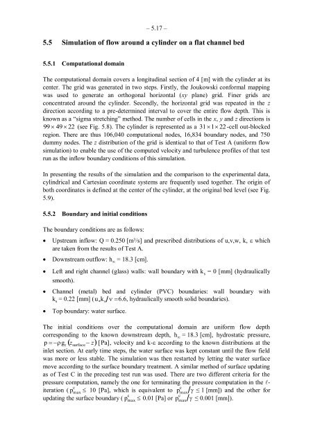
5.5 Simulation of flow around a cylinder on a flat channel bed<br />
5.5.1 Computational domain<br />
The computational domain covers a longitudinal section of 4 [m] with the cylinder at its<br />
center. The grid was generated in two steps. Firstly, the Joukowski conformal mapping<br />
was used to generate an orthogonal horizontal (xy plane) grid. Finer grids are<br />
concentrated around the cylinder. Secondly, the horizontal grid was repeated in the z<br />
direction according to a pre-determined interval to cover the entire flow depth. This is<br />
known as a “sigma stretching” method. The number of cells in the x, y and z directions is<br />
99 � 49 � 22 (see Fig. 5.8). The cylinder is represented as a 31 �1� 22 -cell out-blocked<br />
region. There are thus 106,040 computational nodes, 16,834 boundary nodes, and 750<br />
dummy nodes. The z distribution of the grid is identical to that of Test A (uniform flow<br />
simulation) to enable the use of the computed velocity and turbulence profiles of that test<br />
run as the inflow boundary conditions of this simulation.<br />
In presenting the results of the simulation and the comparison to the experimental data,<br />
cylindrical and Cartesian coordinate systems are frequently used together. The origin of<br />
both coordinates is defined at the center of the cylinder, at the original bed level (see Fig.<br />
5.9).<br />
5.5.2 Boundary and initial conditions<br />
The boundary conditions are as follows:<br />
� Upstream inflow: Q = 0.250 [m 3 /s] and prescribed distributions of u,v,w, k, � which<br />
are taken from the results of Test A.<br />
� Downstream outflow: h ∞ = 18.3 [cm].<br />
� Left and right channel (glass) walls: wall boundary with k s = 0 [mm] (hydraulically<br />
smooth).<br />
� Channel (metal) bed and cylinder (PVC) boundaries: wall boundary with<br />
k s = 0.22 [mm] (u �k s � �6.6, hydraulically smooth solid boundaries).<br />
� Top boundary: water surface.<br />
The initial conditions over the computational domain are uniform flow depth<br />
corresponding to the known downstream depth, h∞ = 18.3 [cm], hydrostatic pressure,<br />
p � ��gz �zsurface � z�<br />
[Pa], velocity and k-� according to the known distributions at the<br />
inlet section. At early time steps, the water surface was kept constant until the flow field<br />
was more or less stable. The simulation was then restarted by letting the water surface<br />
move according to the surface boundary treatment. A similar method of surface updating<br />
as of Test C in the preceding test run was used. There are two different criteria for the<br />
pressure computation, namely the one for terminating the pressure computation in the �-<br />
c<br />
c<br />
iteration ( pmax � 10 [Pa], which is equivalent to pmax � ≤ 1 [mm]) and the other for<br />
c<br />
c<br />
updating the surface boundary ( pmax � 0.01 [Pa] or pmax � ≤ 0.001 [mm]).