
Create successful ePaper yourself
Turn your PDF publications into a flip-book with our unique Google optimized e-Paper software.
– 2.25 –<br />
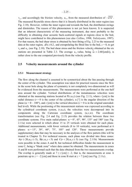
�o , and accordingly the friction velocity, u � , from the measured distribution of �u �� w ��.<br />
The measured Reynolds stress shows that it is linearly distributed in the outer region (see<br />
Fig. 2.10). However, within the inner region and towards the bed, the distribution swings<br />
and diminishes. The reason of this phenomenon is not yet been known. It is suspected<br />
that an inherent characteristic of the measuring instrument, due most probably to the<br />
difficulty in obtaining clear acoustic back-scattered signals at regions close to the bed,<br />
might have contributed to this phenomenon (see also Cellino, 1998; Yulistiyanto, 1997).<br />
For that reason, the bed shear stress is obtained by best fitting of Eq. 2.23 to the measured<br />
data at the outer region, z h � 0.2 , and extrapolating the fitted line to the bed, z = 0, to get<br />
�o and u � (see Fig. 2.10). The bed shear stress and the friction velocity obtained at the six<br />
stations are presented in Table 2.3. The average u �-value, being u� � 2.60 [cm s], is<br />
rather close to the one computed previously from the velocity profile.<br />
2.5 Velocity measurements around the cylinder<br />
2.5.1 Measurement strategy<br />
The flow along the channel is assumed to be symmetrical about the line passing through<br />
the center of the cylinder. This assumption was taken for practical reasons since the flow<br />
in the scour hole along the plane of symmetry is not completely two-dimensional as will<br />
be evidenced from the measurements. The measurements were performed at the one-half<br />
area around the cylinder. Vertical distributions of the instantaneous velocities were<br />
obtained at the measuring stations located at P(r,�,z) (see Fig. 2.11), where r [cm] is the<br />
radial distance (r = 0 is the center of the cylinder), � [°] is the angular direction of the<br />
plane (� = � – 180°), and z [cm] is the vertical direction (z = 0 is in the original unerodedbed<br />
level). While the positioning of the measurement stations was expressed according to<br />
the cylindrical coordinate system, (r,�,z), the velocities were decomposed into its<br />
components along the Cartesian coordinate system, (u,v,w). The coordinate<br />
transformation (see Fig. 2.4 and Eq. 2.13) provides the relation between these two<br />
coordinate systems. Five main radial-planes: � = 0°, 45°, 90°, 135° and 180° (see Fig.<br />
2.11a) were selected in which about 15 to 25 verticals were obtained for each plane.<br />
Additional measurements, with fewer verticals (8 to 10 verticals), were performed at 6<br />
planes: � = 15°, 30°, 60°, 75°, 105° and 120°. These measurements provide<br />
supplementary data that may be necessary in the analyses of the flow pattern (this will be<br />
treated in Chapter 5). For technical reasons, each plane was divided into three zones:<br />
A(r � 20,�, z � 5), B(r,�,z � 5) and C(r � 20,�, z � 5) (see Fig. 2.11b). Measurements<br />
were possible in the zones A and B, but technical difficulties hinder the measurement in<br />
zone C, being a ―blank zone‖ where data cannot be obtained. The measurements in zones<br />
A and B were performed such that the data obtained from the two measurements overlap.<br />
The overlap is generally made at 7 ≥ z [cm] ≥ –2, that is, the measurements at zone A<br />
penetrate up to z = –2 [cm] and those in zone B start at z = 7 [cm] (see Fig. 2.11c).