Varian Linatron High-Energy X-ray Applications 2007
Varian Linatron High-Energy X-ray Applications 2007
Varian Linatron High-Energy X-ray Applications 2007

You also want an ePaper? Increase the reach of your titles
YUMPU automatically turns print PDFs into web optimized ePapers that Google loves.
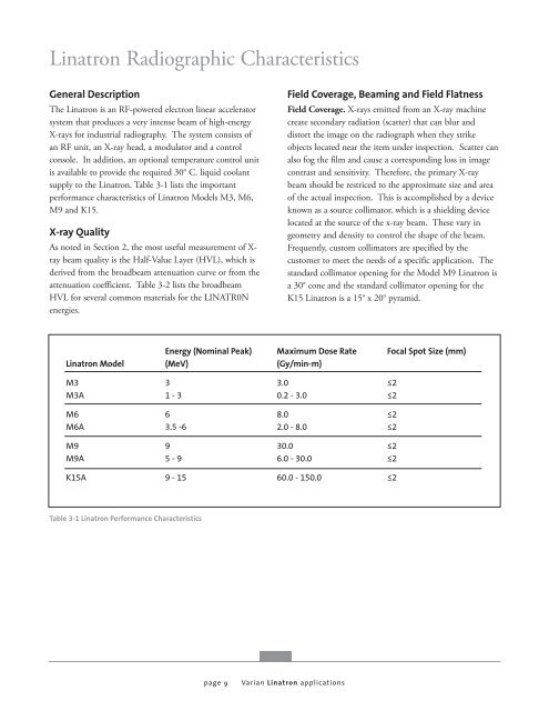
<strong>Linatron</strong> Radiographic Characteristics<br />
General Description<br />
The <strong>Linatron</strong> is an RF-powered electron linear accelerator<br />
system that produces a very intense beam of high-energy<br />
X-<strong>ray</strong>s for industrial radiography. The system consists of<br />
an RF unit, an X-<strong>ray</strong> head, a modulator and a control<br />
console. In addition, an optional temperature control unit<br />
is available to provide the required 30° C. liquid coolant<br />
supply to the <strong>Linatron</strong>. Table 3-1 lists the important<br />
performance characteristics of <strong>Linatron</strong> Models M3, M6,<br />
M9 and K15.<br />
X-<strong>ray</strong> Quality<br />
As noted in Section 2, the most useful measurement of X<strong>ray</strong><br />
beam quality is the Half-Value Layer (HVL), which is<br />
derived from the broadbeam attenuation curve or from the<br />
attenuation coefficient. Table 3-2 lists the broadbeam<br />
HVL for several common materials for the LINATR0N<br />
energies.<br />
<strong>Linatron</strong> Model<br />
M3<br />
M3A<br />
M6<br />
M6A<br />
M9<br />
M9A<br />
K15A<br />
Table 3-1 <strong>Linatron</strong> Performance Characteristics<br />
<strong>Energy</strong> (Nominal Peak)<br />
(MeV)<br />
3<br />
1 - 3<br />
6<br />
3.5 -6<br />
9<br />
5 - 9<br />
9 - 15<br />
page 9<br />
Field Coverage, Beaming and Field Flatness<br />
Field Coverage. X-<strong>ray</strong>s emitted from an X-<strong>ray</strong> machine<br />
create secondary radiation (scatter) that can blur and<br />
distort the image on the radiograph when they strike<br />
objects located near the item under inspection. Scatter can<br />
also fog the film and cause a corresponding loss in image<br />
contrast and sensitivity. Therefore, the primary X-<strong>ray</strong><br />
beam should be restriced to the approximate size and area<br />
of the actual inspection. This is accomplished by a device<br />
known as a source collimator, which is a shielding device<br />
located at the source of the x-<strong>ray</strong> beam. These vary in<br />
geometry and density to control the shape of the beam.<br />
Frequently, custom collimators are specified by the<br />
customer to meet the needs of a specific application. The<br />
standard collimator opening for the Model M9 <strong>Linatron</strong> is<br />
a 30° cone and the standard collimator opening for the<br />
K15 <strong>Linatron</strong> is a 15° x 20° pyramid.<br />
Maximum Dose Rate<br />
(Gy/min-m)<br />
3.0<br />
0.2 - 3.0<br />
8.0<br />
2.0 - 8.0<br />
30.0<br />
6.0 - 30.0<br />
60.0 - 150.0<br />
<strong>Varian</strong> <strong>Linatron</strong> applications<br />
Focal Spot Size (mm)<br />
≤2<br />
≤2<br />
≤2<br />
≤2<br />
≤2<br />
≤2<br />
≤2


![[MSDS 126] Dow Corning 200 Fluid, 5 CST Part Number ... - Varian](https://img.yumpu.com/5104917/1/190x245/msds-126-dow-corning-200-fluid-5-cst-part-number-varian.jpg?quality=85)