Varian Linatron High-Energy X-ray Applications 2007
Varian Linatron High-Energy X-ray Applications 2007
Varian Linatron High-Energy X-ray Applications 2007

You also want an ePaper? Increase the reach of your titles
YUMPU automatically turns print PDFs into web optimized ePapers that Google loves.
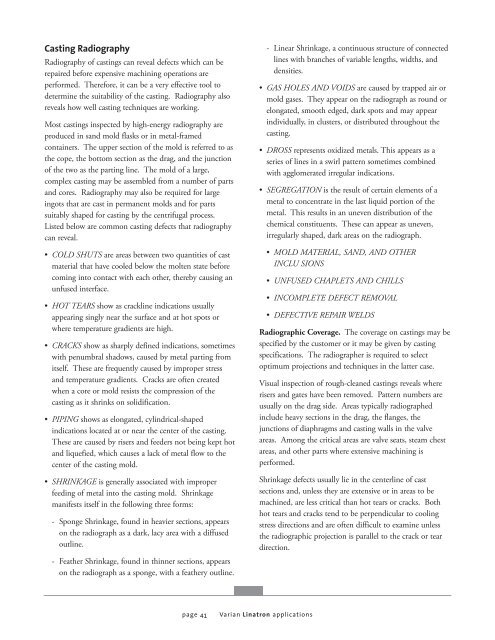
Casting Radiography<br />
Radiography of castings can reveal defects which can be<br />
repaired before expensive machining operations are<br />
performed. Therefore, it can be a very effective tool to<br />
determine the suitability of the casting. Radiography also<br />
reveals how well casting techniques are working.<br />
Most castings inspected by high-energy radiography are<br />
produced in sand mold flasks or in metal-framed<br />
containers. The upper section of the mold is referred to as<br />
the cope, the bottom section as the drag, and the junction<br />
of the two as the parting line. The mold of a large,<br />
complex casting may be assembled from a number of parts<br />
and cores. Radiography may also be required for large<br />
ingots that are cast in permanent molds and for parts<br />
suitably shaped for casting by the centrifugal process.<br />
Listed below are common casting defects that radiography<br />
can reveal.<br />
• COLD SHUTS are areas between two quantities of cast<br />
material that have cooled below the molten state before<br />
coming into contact with each other, thereby causing an<br />
unfused interface.<br />
• HOT TEARS show as crackline indications usually<br />
appearing singly near the surface and at hot spots or<br />
where temperature gradients are high.<br />
• CRACKS show as sharply defined indications, sometimes<br />
with penumbral shadows, caused by metal parting from<br />
itself. These are frequently caused by improper stress<br />
and temperature gradients. Cracks are often created<br />
when a core or mold resists the compression of the<br />
casting as it shrinks on solidification.<br />
• PIPING shows as elongated, cylindrical-shaped<br />
indications located at or near the center of the casting.<br />
These are caused by risers and feeders not being kept hot<br />
and liquefied, which causes a lack of metal flow to the<br />
center of the casting mold.<br />
• SHRINKAGE is generally associated with improper<br />
feeding of metal into the casting mold. Shrinkage<br />
manifests itself in the following three forms:<br />
- Sponge Shrinkage, found in heavier sections, appears<br />
on the radiograph as a dark, lacy area with a diffused<br />
outline.<br />
- Feather Shrinkage, found in thinner sections, appears<br />
on the radiograph as a sponge, with a feathery outline.<br />
page 41<br />
<strong>Varian</strong> <strong>Linatron</strong> applications<br />
- Linear Shrinkage, a continuous structure of connected<br />
lines with branches of variable lengths, widths, and<br />
densities.<br />
• GAS HOLES AND VOIDS are caused by trapped air or<br />
mold gases. They appear on the radiograph as round or<br />
elongated, smooth edged, dark spots and may appear<br />
individually, in clusters, or distributed throughout the<br />
casting.<br />
• DROSS represents oxidized metals. This appears as a<br />
series of lines in a swirl pattern sometimes combined<br />
with agglomerated irregular indications.<br />
• SEGREGATION is the result of certain elements of a<br />
metal to concentrate in the last liquid portion of the<br />
metal. This results in an uneven distribution of the<br />
chemical constituents. These can appear as uneven,<br />
irregularly shaped, dark areas on the radiograph.<br />
• MOLD MATERIAL, SAND, AND OTHER<br />
INCLU SIONS<br />
• UNFUSED CHAPLETS AND CHILLS<br />
• INCOMPLETE DEFECT REMOVAL<br />
• DEFECTIVE REPAIR WELDS<br />
Radiographic Coverage. The coverage on castings may be<br />
specified by the customer or it may be given by casting<br />
specifications. The radiographer is required to select<br />
optimum projections and techniques in the latter case.<br />
Visual inspection of rough-cleaned castings reveals where<br />
risers and gates have been removed. Pattern numbers are<br />
usually on the drag side. Areas typically radiographed<br />
include heavy sections in the drag, the flanges, the<br />
junctions of diaphragms and casting walls in the valve<br />
areas. Among the critical areas are valve seats, steam chest<br />
areas, and other parts where extensive machining is<br />
performed.<br />
Shrinkage defects usually lie in the centerline of cast<br />
sections and, unless they are extensive or in areas to be<br />
machined, are less critical than hot tears or cracks. Both<br />
hot tears and cracks tend to be perpendicular to cooling<br />
stress directions and are often difficult to examine unless<br />
the radiographic projection is parallel to the crack or tear<br />
direction.


![[MSDS 126] Dow Corning 200 Fluid, 5 CST Part Number ... - Varian](https://img.yumpu.com/5104917/1/190x245/msds-126-dow-corning-200-fluid-5-cst-part-number-varian.jpg?quality=85)