Varian Linatron High-Energy X-ray Applications 2007
Varian Linatron High-Energy X-ray Applications 2007
Varian Linatron High-Energy X-ray Applications 2007

You also want an ePaper? Increase the reach of your titles
YUMPU automatically turns print PDFs into web optimized ePapers that Google loves.
• Moving the film farther from the object (increasing “TI’)<br />
reduces scatter, which improves image quality.<br />
HOWEVER,<br />
Exposure time and geometric unsharpness are increased.<br />
• Increasing the source-to-object distance provides greater<br />
area coverage and reduces geometric unsharpness.<br />
HOWEVER,<br />
Exposure time increases by the inverse square law.<br />
• Using composite metal-phosphor screens shortens<br />
exposure times and provides higher contrast in the<br />
image.<br />
HOWEVER,<br />
Composite metal-phosphor screens result in increased<br />
graininess and a loss of sharpness and detail resolution.<br />
Unsharpness in a radiograph can be defined as blurring of<br />
image edges. This causes a loss of fine crack definition,<br />
image detail, and penetrameter (Image Quality Indicator)<br />
detail. Unsharpness and lack of contrast are not<br />
synonymous. Film contrast is the difference in film<br />
density between two areas of a radiograph. A film may<br />
have high contrast but lack sharpness because of image<br />
edge blurring, and vice versa. Good image quality needs<br />
sharpness and high contrast for good radiographic<br />
sensitivity.<br />
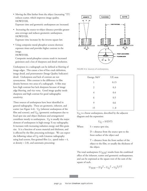
Three sources of unsharpness have been identified in<br />
general radiography. These are geometric, inherent, and<br />
scatter (see Figure 4-6). U F (inherent unsharpness of the<br />
film and screens), and U G (geometric unsharpness due to<br />
focal spot size and object thickness and arrangement)<br />
contribute mostly to unsharpness. U F is usually the major<br />
element of unsharpness in high-energy X-<strong>ray</strong> radiography.<br />
It increases with increasing radiation energy and film grain<br />
size. It is a function of screen material and thickness, and<br />
is affected by the film processing technique. We can expect<br />
the following values of U F with <strong>Linatron</strong> radiography<br />
using lead screens, fine-grained film (i.e., speed index = 4,<br />
at density = 2.0), and automatic processing:<br />
page 23<br />
FIGURE 4-6. Sources of unsharpness.<br />
<strong>Energy</strong>, MeV UF, mm<br />
1 0.15<br />
2 0.3<br />
4 0.4<br />
6 0.5<br />
9 0.6<br />
15 1 .0<br />
U G is a linear unsharpness, described by the adjacent<br />
diagram and the expression:<br />
U G = S/(D/T)<br />
Where S = source spot size,<br />
D = distance from the source spot to the<br />
front surface of the object and<br />
T = distance from the front surface of the<br />
object to the film, or usually the thickness of<br />
the object.<br />
The total unsharpness (UTOT ) results from the combined<br />
effect of the inherent, scatter and geometric unsharpnesses,<br />
and can be expressed as the square root of the sum of the<br />
square of each.<br />
UTOT = (U 2<br />
F + UG2 + US2 ) 1/2<br />
<strong>Varian</strong> <strong>Linatron</strong> applications


![[MSDS 126] Dow Corning 200 Fluid, 5 CST Part Number ... - Varian](https://img.yumpu.com/5104917/1/190x245/msds-126-dow-corning-200-fluid-5-cst-part-number-varian.jpg?quality=85)