Varian Linatron High-Energy X-ray Applications 2007
Varian Linatron High-Energy X-ray Applications 2007
Varian Linatron High-Energy X-ray Applications 2007

You also want an ePaper? Increase the reach of your titles
YUMPU automatically turns print PDFs into web optimized ePapers that Google loves.
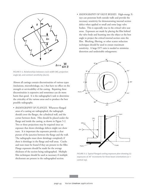
FIGURE 5-1. Relationships between crack width (W), projection<br />
angle (ø), and contrast sensitivity (Δx/x).<br />
Almost all castings contain discontinuities of various types<br />
(inclusions, microshrinkage, etc.) that have no effect on the<br />
strength or serviceability of the casting. Repairing these<br />
discontinuities is expensive and sometimes can do more<br />
harm than good. It is the radiographer’s task to determine<br />
the criticality of the various areas and to produce the best<br />
possible radiographs.<br />
• RADIOGRAPHY OF FLANGES. Whenever flanged<br />
areas of a casting are radiographed, the radiograph<br />
should cover the flanges, the cylindrical wall, and the<br />
corner between them. Film should be placed under the<br />
flange and inside the casting, as shown in Figure 5-2.<br />
Two or three projections may be required since an<br />
exposure that shows shrinkage defects might not show<br />
tears. It is important the exposures provide a clear<br />
picture of the junction between the flange and the wall.<br />
The radiographs must show shrinkage completely if<br />
there is shrinkage in the flange and wall areas. Cracks<br />
and tears must be found if they are present in the fillet.<br />
Flange exposures should be made for the average<br />
thickness of the section being radiographed. Multiple<br />
film techniques should be used as necessary if multiple<br />
thicknesses are present in the radiographed section.<br />
page 43<br />
• RADIOGRAPHY OF VALVE BODIES. <strong>High</strong>-energy X<strong>ray</strong>s<br />
can penetrate both outside walls and provide the<br />
necessary sensitivity for demonstrating internal section<br />
defect when applied to small and some large valve<br />
bodies. This is especially true in the critical valve seat<br />
areas. Exposures are made by placing the film behind<br />
the valve body and beaming into the object at the best<br />
angle to project the critical internal section onto the<br />
film. Blocking, filtering, or other scatter reduction<br />
techniques should be used to ensure maximum<br />
sensitivity. A large D/T ratio is needed to minimize<br />
distortion and undesirable enlargement.<br />
FIGURE 5-2. Typical flanged casting exposure plan showing 12<br />
exposures at 30˚ increments for three beam orientations (cr =<br />
central <strong>ray</strong>).<br />
<strong>Varian</strong> <strong>Linatron</strong> applications


![[MSDS 126] Dow Corning 200 Fluid, 5 CST Part Number ... - Varian](https://img.yumpu.com/5104917/1/190x245/msds-126-dow-corning-200-fluid-5-cst-part-number-varian.jpg?quality=85)