Varian Linatron High-Energy X-ray Applications 2007
Varian Linatron High-Energy X-ray Applications 2007
Varian Linatron High-Energy X-ray Applications 2007

Create successful ePaper yourself
Turn your PDF publications into a flip-book with our unique Google optimized e-Paper software.
Grain Radiography Coverage Requirements. Contrast<br />
sensitivities of better than 1% can be achieved routinely<br />
with the <strong>Linatron</strong> using optimum radiographic production<br />
techniques. Defects such as voids and gross density<br />
variations in the solid propellant are readily detected at that<br />
sensitivity. The simplest radiographic procedure (e.g., one<br />
exposure through the grain or two exposures, one at 0˚ and<br />
the second at 90˚ may be used when these are the only<br />
concern. However, cracks and separations are also of great<br />
concern in rocket motors.<br />
Cracks with widths of 1 to 5 mils (0.03 - 0.13 mm) are<br />
detected only when they are aligned with the radiation<br />
source. Most propellants with cracks will open to a width<br />
of 10 to 30 mils (0.25 - 0.76 mm) minimum. At these<br />
widths cracks can readily be detected at almost any angle to<br />
the radiation, and through large thicknesses of propellant.<br />
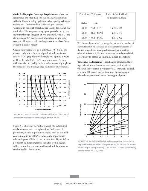
FIGURE 5-7. Visualization of crack-like defects, as a function of<br />
propellant thickness and crack angle, for x/x = 0.2%.<br />
Figure 5-7 illustrates the width of crack-like defects that<br />
can be demonstrated through various thicknesses of<br />
propellant, at various projection angles, with an assumed<br />
contrast sensitivity of 0.2%. Refer to the approximate<br />
relationship Δx = W/ø. It can be seen from Figure 5-7, as<br />
propellant thickness increases, the ratio W/ø increases,<br />
which means that the same width crack will be shown at<br />
smaller angles. For example,<br />
page 50<br />
Propellant Thickness Ratio of Crack Width<br />
to Projection Angle<br />
inches cm<br />
<strong>Varian</strong> <strong>Linatron</strong> applications<br />
30-36 76.2 - 91.4 W/ø ≈ 1.0<br />
40-50 101.6 - 127.0 W/ø ≈ 1.5<br />
50-60 127.0 - 152.4 W/ø ≈ 2.0<br />
To observe the required rocket grain cracks, the number of<br />
exposures must be increased as the diameter increases. If<br />
the technique being used produces contrast sensitivity<br />
other thanAx/x = 0.2%, the procedures must be modified<br />
accordingly to obtain an equivalent defect detectability.<br />
Tangential Radiography. Propellant-to-insulation (liner<br />
separations) in the domes are considered critical defects<br />
wherever they occur in a rocket motor. Separations as small<br />
as 2 mils (0.05 mm) can be shown on the radiograph,<br />
when the separation occurs at the tangential point.<br />
FIGURE 5-8. Probability (P) of detecting propellant to insulation<br />
separation versus number of exposures (N) for various circumferential<br />
lengths of separation (Lc , for 54-inch (137 cm) diameter (D),<br />
rocket motor, P = Lc/n - D N.


![[MSDS 126] Dow Corning 200 Fluid, 5 CST Part Number ... - Varian](https://img.yumpu.com/5104917/1/190x245/msds-126-dow-corning-200-fluid-5-cst-part-number-varian.jpg?quality=85)