Varian Linatron High-Energy X-ray Applications 2007
Varian Linatron High-Energy X-ray Applications 2007
Varian Linatron High-Energy X-ray Applications 2007

Create successful ePaper yourself
Turn your PDF publications into a flip-book with our unique Google optimized e-Paper software.
Drilled Hole Plaque Penetrameter Sensitivity. The<br />
drilled hole plaque is the standard American penetrameter<br />
for all radiography. It consists of a small rectangular strip<br />
of material with three drilled holes. Thickness of the<br />
penetrameter is specified as 1%, 2%, or more, of the object<br />
thickness. The three hole diameters are equal to 1 x T, 2 x<br />
T, and 4 x T where the thickness of the penetrameter “T”.<br />
Sensitivity is described in terms of the thickness percent (1,<br />
2, 4) and the required hole size that must be discerned.<br />
Example<br />
2-2T is the standard way to describe a penetrameter whose<br />
thickness must be 2% of the object thickness and whose 2<br />
x T hole must be seen on the film.<br />
Drilled hole sensitivity data for each <strong>Linatron</strong> show that all<br />
sources should demonstrate better than 1% sensitivity<br />
above 2 inches (50.8 mm) of steel, up to 10 HVLs, and<br />
better than 2% for thicknesses down to 1 inch (25.4 mm).<br />
Radiographic Sensitivity. Radiographic sensitivity refers<br />
to the ability to see and recognize a variety of defects and<br />
other internal conditions in the radiograph in this manual.<br />
Standard penetrameters provide an indicator of the level of<br />
image quality that is achieved with a particular<br />
radiographic technique used. Penetrameters do not,<br />
however, give defect size. Penetrameters must be placed on<br />
the source side of an object since the image improves as the<br />
defect occurs closer to the film.<br />
Exposure Curves<br />
The plot of exposure level that corresponds to a specific<br />
film density (2.0 for example) for each thickness of<br />
material is called an exposure curve. Exposure curves<br />
should be made for the <strong>Linatron</strong> after it is completely<br />
operational for all applications. Such curves represent<br />
operational data that are indicative of the operating<br />
characteristics of the setup. Subsequent exposure curves for<br />
the same setup should provide consistent results.<br />
page 25<br />
Established exposure curves also allow the radiographer to<br />
simplify the exposure calculation process. With these<br />
curves, the radiographer only needs to look up the required<br />
exposure level for that thickness and make the exposure. If<br />
the source-to-film distance must be changed, using the<br />
inverse square law provides the new exposure level. A<br />
change to a different film can lead to an additional<br />
adjustment of exposure level using the relative speed table.<br />
Method for Making Exposure Curves. This process<br />
involves making a series of test exposures of an object with<br />
uniform density but varying thickness. Typically, a wedge<br />
or stair-step shaped block is used in conjunction with<br />
additional slabs of uniform thickness. Because exposure<br />
time can be represented as a straight line on semi-log graph<br />
paper, at least two measurements are needed to establish<br />
this line.<br />
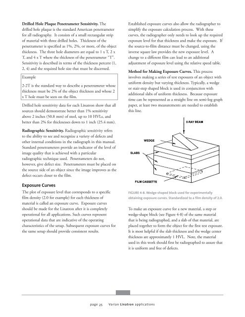
FIGURE 4-8. Wedge-shaped block used for experimentally<br />
obtaining exposure curves. Standardized to a film density of 2.0.<br />
To make an exposure curve for a new material, a step or<br />
wedge-shape block (see Figure 4-8) of the same material<br />
that is being radiographed, and a slab of that material, are<br />
placed together to form the object for the first test exposure.<br />
It is most helpful if the slab thickness and the wedge center<br />
thickness are approximately 1 HVL. Note, the material<br />
used in this work should first be radiographed to assure that<br />
it is uniform and free of defects.<br />
<strong>Varian</strong> <strong>Linatron</strong> applications


![[MSDS 126] Dow Corning 200 Fluid, 5 CST Part Number ... - Varian](https://img.yumpu.com/5104917/1/190x245/msds-126-dow-corning-200-fluid-5-cst-part-number-varian.jpg?quality=85)