ACTA TECHNICA CORVINIENSIS – BULLETIN of ENGINEERINGmechanisms for customization: profiles andstereotype.UML is not a development method by itself,however, it was designed to be compatible withthe leading object-oriented softwaredevelopment methods of its time. Since UML hasevolved, some of these methods have beenrecast to take advantage of the new notations(for example OMT), and new methods havebeen created based on UML. The best known isIBM Rational Unified Process (RUP). There aremany other UML-based methods like AbstractionMethod, Dynamic Systems DevelopmentMethod, and others, designed to provide morespecific solutions, or achieve differentobjectives.It is very important to distinguish between theUML model and the set of diagrams of a system.A diagram is a partial graphical representationof a system's model. The model also contains a"semantic backplane" — documentation such aswritten use cases that drive the model elementsand diagrams.UML diagrams represent two different views of asystem model [2]:Static view: Emphasizes the static structureof the system using objects, attributes,operations and relationships. The structuralview includes class diagrams and compositestructure diagrams.Dynamic view: Emphasizes the dynamicbehavior of the system by showingcollaborations among objects and changesto the internal states of objects. This viewincludes sequence diagrams, activitydiagrams and state machine diagrams.UML models can be exchanged amongSEQUENCE DIAGRAMSA sequence diagram in Unified ModelingLanguage (UML) is a kind of interaction diagramthat shows how processes operate with oneanother and in what order [3]. It is a construct ofa Message Sequence Chart. Sequence diagramsare sometimes called Event-trace diagrams,event scenarios, and timing diagrams.A sequence diagram shows, as parallel verticallines, different processes or objects that livesimultaneously, and, as horizontal arrows, themessages exchanged between them, in the orderin which they occur. This allows thespecification of simple runtime scenarios in agraphical manner.The UML 2.0 Sequence Diagram supports similarnotation to the UML 1.x Sequence Diagram withadded support for modeling variations to thestandard flow of events.If the lifeline is that of an object, it is underlined.Note that leaving the instance name blank canrepresent anonymous and unnamed instances.In order to display interaction, messages areused. These are horizontal arrows with themessage name written above them. Solid arrowswith full heads are synchronous calls, solidarrows with stick heads are asynchronous callsand dashed arrows with stick heads are returnmessages. This definition is true as of UML 2,considerably different from UML 1.x.Activation boxes, or method-call boxes, areopaque rectangles drawn on top of lifelines torepresent that processes are being performed inresponse to the message (ExecutionSpecifications in UML). Objects calling methodson themselves use messages and add newactivation boxes on top of any others to indicatea further level of processing.When an object is destroyed, an X is drawn ontop of the lifeline, and the dashed line ceases tobe drawn below it (this is not the case in the firstexample though). It should be the result of amessage, either from the object itself, or another.A message sent from outside the diagram can berepresented by a message originating from afilled-in circle ("found message" in UML) or froma border of sequence diagram ("gate" in UML).UML 2 has introduced significant improvementsto the capabilities of sequence diagrams [4]. Mostof these improvements are based on the idea ofinteraction fragments which represent smallerpieces of an enclosing interaction. Multipleinteraction fragments are combined to create avariety of combined fragments, which are thenused to model interactions that includeparallelism, conditional branches, optionalinteractions etc.Some systems have simple dynamic behaviorthat can be expressed in terms of specificsequences of messages between a small, fixednumber of objects or processes. In such casessequence diagrams can completely specify thesystem's behavior. Often, behavior is morecomplex, e.g. when the set of communicatingobjects is large or highly variable, when there aremany branch points (e.g. exceptions), when502008/ACTA TECHNICA CORVINIENSIS/Tome I
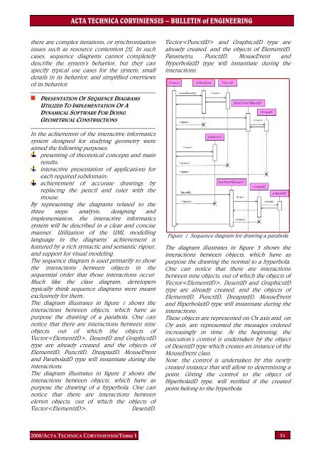
ACTA TECHNICA CORVINIENSIS – BULLETIN of ENGINEERINGthere are complex iterations, or synchronizationissues such as resource contention [5]. In suchcases, sequence diagrams cannot completelydescribe the system's behavior, but they canspecify typical use cases for the system, smalldetails in its behavior, and simplified overviewsof its behavior.Vector and Graphics2D type arealready created, and the objects of Element2D,Parametru, Punct2D, MouseEvent andHyperbola2D type will instantiate during theinteractions.PRESENTATION OF SEQUENCE DIAGRAMSUTILIZED TO IMPLEMENTATION OF ADYNAMICAL SOFTWARE FOR DOINGGEOMETRICAL CONSTRUCTIONSIn the achievemnt of the interactive informaticssystem designed for studying geometry wereaimed the following purposes:presenting of theoretical concepts and mainresults;interactive presentation of applications foreach required subdomain;achievement of accurate drawings byreplacing the pencil and ruler with themouse.By representing the diagrams related to thethree steps: analysis, designing andimplementation, the interactive informaticssystem will be described in a clear and concisemanner. Utilization of the UML modellinglanguage in the diagrams’ achievement isfeatured by a rich syntactic and semantic rigour,and support for visual modeling.The sequence diagram is used primarily to showthe interactions between objects in thesequential order that those interactions occur.Much like the class diagram, developerstypically think sequence diagrams were meantexclusively for them..The diagram illustrates in figure 1 shows theinteractions between objects, which have aspurpose the drawing of a parabola. One cannotice that there are interactions between nineobjects, out of which the objects ofVector, Desen2D and Graphics2Dtype are already created, and the objects ofElement2D, Punct2D, Dreapta2D, MouseEventand Parabola2D type will instantiate during theinteractions.The diagram illustrates in figure 2 shows theinteractions between objects, which have aspurpose the drawing of a hyperbola. One cannotice that there are interactions betweeneleven objects, out of which the objects ofVector,Desen2D,Figure 1. Sequence diagram for drawing a parabolaThe diagram illustrates in figure 3 shows theinteractions between objects, which have aspurpose the drawing the normal to a hyperbola.One can notice that there are interactionsbetween nine objects, out of which the objects ofVector, Desen2D and Graphics2Dtype are already created, and the objects ofElement2D, Punct2D, Dreapta2D, MouseEventand Hiperbola2D type will instantiate during theinteractions.These objects are represented on Ox axis and, onOy axis, are represented the messages orderedincreasingly in time. At the beginning, theexecution’s control is undertaken by the objectof Desen2D type which creates an instance of theMouseEvent class.Now, the control is undertaken by this newlycreated instance that will allow to determining apoint. Giving the control to the object ofHiperbola2D type, will verified if the createdpoint belong to the hyperbola.2008/ACTA TECHNICA CORVINIENSIS/Tome I 51