

PA7300 Instruction Manual - TECO-Westinghouse Motor Company
PA7300 Instruction Manual - TECO-Westinghouse Motor Company
PA7300 Instruction Manual - TECO-Westinghouse Motor Company

Create successful ePaper yourself
Turn your PDF publications into a flip-book with our unique Google optimized e-Paper software.
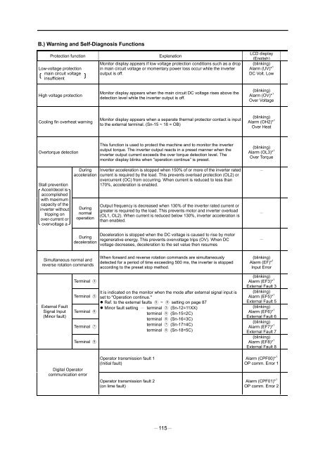
B.) Warning and Self-Diagnosis FunctionsProtection functionLow-voltage protectionmain circuit voltageinsufficientExplanationMonitor display appears if low voltage protection conditions such as a dropin main circuit voltage or momentary power loss occur while the inverteroutput is off.LCD display(English)(blinking)Alarm (UV)* 1DC Volt. LowHigh voltage protectionMonitor display appears when the main circuit DC voltage rises above thedetection level while the inverter output is off.(blinking)Alarm (OV)* 1Over VoltageCooling fin overheat warningMonitor display appears when a separate thermal protector contact is inputto the external terminal. (Sn-15 ~ 18 = OB)(blinking)Alarm (OH2)* 1Over HeatOvertorque detectionThis function is used to protect the machine and to monitor the inverteroutput torque. The inverter output reacts in a preset manner when theinverter output current exceeds the over torque detection level. Themonitor display blinks when “operation continue” is preset.(blinking)Alarm (OL3)* 1Over TorqueStall preventionAccel/decel isaccomplishedwith maximumcapacity of theinverter withouttripping onover-current orovervoltage aDuringaccelerationDuringnormaloperationDuringdecelerationInverter acceleration is stopped when 150% of or more of the inverter ratedcurrent is required by the load. This prevents overload protection (OL2) orovercurrent (OC) from occurring. When current is reduced to less than170%, acceleration is enabled.Output frequency is decreased when 130% of the inverter rated current orgreater is required by the load. This prevents motor and inverter overload(OL1, OL2). When current is reduced below 130%, inverter acceleration isthan enabled.Deceleration is stopped when the DC voltage is caused to rise by motorregenerative energy. This prevents overvoltage trips (OV). When DCvoltage decreases, deceleration to the set value then resumesSimultaneous normal andreverse rotation commandsWhen forward and reverse rotation commands are simultaneouslydetected for a period of time exceeding 500 ms, the inverter is stoppedaccording to the preset stop method.(blinking)Alarm (EF)* 1Input ErrorExternal FaultSignal Input(Minor fault)Terminal 3Terminal 5Terminal 6Terminal 7Terminal 8It is indicated on the monitor when the mode after external signal input isset to "Operation continue."Ref. to the external faults 5 ~ 8 setting on page 87Minor fault setting terminal 3 (Sn-12=11XX)terminal 5 (Sn-15=2C)terminal 6 (Sn-16=3C)terminal 7 (Sn-17=4C)terminal 8 (Sn-18=5C)(blinking)Alarm (EF3)* 1External Fault 3(blinking)Alarm (EF5)* 1External Fault 5(blinking)Alarm (EF6)* 1External Fault 6(blinking)Alarm (EF7)* 1External Fault 7(blinking)Alarm (EF8)* 1External Fault 8Digital Operatorcommunication errorOperator transmission fault 1(Initial fault)Operator transmission fault 2(on lime fault)Alarm (CPF00)* 1OP comm. Error 1Alarm (CPF01)* 1OP comm. Error 2115


