

PA7300 Instruction Manual - TECO-Westinghouse Motor Company
PA7300 Instruction Manual - TECO-Westinghouse Motor Company
PA7300 Instruction Manual - TECO-Westinghouse Motor Company

You also want an ePaper? Increase the reach of your titles
YUMPU automatically turns print PDFs into web optimized ePapers that Google loves.
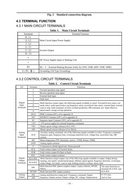
Fig. 2Standard connection diagram.4.3 TERMINAL FUNCTION4.3.1 MAIN CIRCUIT TERMINALSTerminalsR / L1S / L2T / L3U / T1V / T2W / T3Table 1. Main Circuit TerminalsMain Circuit Input Power SupplyInverter OutputTerminal FunctionB2DC Power Supply Input or Braking UnitB2External Braking Resistor (Only for 220V 25HP, 440V 25HP, 30HP)E ( PE, ) Grounding (3rd Type Grounding)4.3.2 CONTROL CIRCUIT TERMINALSTable 2. Control Circuit TerminalsI/O Terminal Functions1 Forward operation-stop signal.DigitalInputTerminalsAnalogInputTerminalsDigitalOutputTerminalsAnalogOutputT i l2 Reverse operation-stop signal.3 External fault input.4 Fault reset.5Multi-function contact input: the following signals available to select. Forward/reverse select, run6 mode select, multi-speed select, jog frequency select, accel/decel time select, external fault, external7 coast to stop, hold command, inverter overheat prediction, DB command, aux. Input effective,speed search, energy-saving operation.824VG SINK Common (0V), ref to appendix D.24V SOURCE Common (24V), ref to appendix D.SC Sequence input Common (24V), ref to appendix D.+15V +15V power supply for external frequency command.VINAINMaster speed voltage reference (0 to 10V).Master speed current reference (4 to 20mA).Auxiliary analog command: one of the following signals available to select. Frequency command,AUX frequency gain, frequency bias, overtorque detection level, voltage bias, accel/decel rate, DBcurrent.MT <strong>Motor</strong> temperature PTC thermistor. (active: 1330, Return: 550)GNDER3AR3BR3CR2A-R2CR1A-R1CD01DCOMA01A02Analog signal common.Connection to shield signal lead. (frame ground)Fault contact output A (Closed at fault).Fault contact output B (Open at fault).Fault contact output common.Multi-function contact output: one of the following signals available to output. Output duringrunning, zero speed, synchronized speed, arbitrary speed agreed, frequency detection, overtorque,undervoltage, run mode, coast to stop, braking resistor overheat, alarm, fault.Multi-function PHC (photo-coupler) output 1 (open collector, 48VDC,50mA)Multi-function PHC output common.Analog multifunction output port: Frequency command, Outputfrequency, Output current, Output voltage, DC voltage, Output power.11The same functions asterminals R1A-R1C andR2A-R2C0~11V max.2mA or less


