G. PERIPHERAL UNIT NOTES Installation and selection of molded-case circuit breaker ————————————On the input power side, a molded case circuit breaker (MCCB) to protect inverter primary wiring should be installed. The inverterpower factor (depending on power voltage, output frequency, and load) must be taken into account for selecting the MCCB. Forstandard selection, see page 13. If a full electromagnetic MCCB is to be used, select a larger capacity because the operatingcharacteristics are altered by harmonic current. A leakage current breaker of inverter use is recommended. Use of input side magnetic contactor ————————————————————The inverter can be used without an input side magnetic contactor (MC). An input MC can be used to prevent an automatic restartafter recovery from an external power loss during remote control operation. However, do not use the MC frequently for start/stopoperation, or it will lead to a reduced reliability. When the digital operator is used, automatic restart after power failure is disabled sothat MC starting is impossible. Although the MC can stop the inverter, regeneration braking is disabled and the motor coasts to stop. Use of secondary magnetic contactor ————————————————————In general, magnetic contactors on the output of the inverter for motor control should not be used. Starting a motor with the inverterrunning will cause large surge currents and the inverter overcurrent protector to be triggered. If an MC is used for switching tocommercial power supply, switch MC after the inverter and the motor stop. To switch during motor rotation, use the speed searchfunction. Use of overload relay ———————————————————————————The inverter includes an electronic thermal protective function to protect the motor from overheating. If more than one motor is drivenwith a single inverter or when a multi-pole motor is used, place an overload relay between the inverter and the motor. Set 1 to the firstposition of Sn-14 (xxx1), and set the overload relay to the current nameplate value at 50Hz, or 1.1 times of that at 60 Hz. Power-factor improvement (elimination of phase advance capacitor) ———————To improve the power-factor, install an AC reactor on the inverter's primary side. Power-factor improvement capacitors or surgesuppressors on the inverter output side will be damaged by the harmonic component in the inverter output. Also, the overcurrentcaused in the inverter output will trigger the overcurrent protection. To avoid this, do not use capacitors or surge suppressors in theinverter's output. To improve the power-factor, install an AC reactor on the inverter primary side. Radio frequency interference ————————————————————————Because the inverter I/O (main circuit) contains a higher harmonics component, it may emit RFI noise to communication equipment(AM radio, etc.) near the inverter. Use a noise filter to decrease the noise. Use of a metallic conduit between the inverter and motorand grounding the conduit is also effective. Proper routing of input and output leads is also recommended. Wire thickness and cable length ———————————————————————If the inverter is connected to a distant motor, (especially when low frequency is output,) motor torque decreases because of voltagedrop in the cable. Use sufficiently heavy wire.When a digital operator is to be installed separately from the inverter, use the <strong>TECO</strong> connection cable (option). For remote controlwith analog signals, connect the operating pot or operating signal terminal and the inverter within 30m of the inverter. The cable mustbe routed separately from power circuits (main circuit and relay sequence circuit) so that it is not subjected to inductive interferenceby other equipment. If frequencies are set not only from the digital operator but also with external frequency controller, use twistedpair shielded wire as shown in the following figure and connect the shielding to terminal E, not to the ground.FREQUENCYCONTROLLER2k13 0 TO +10V24 TO 20mA P0 TO +10V0V2kPPE+15VVINAINSPEED SETTING POWER SUPPLY+15V 200mASHIELDED INSULATED WIRECONNECTION TERMINALAUXGNDMASTER SPEED REFERENCE0 - 10V (20k)MASTER SPEED REFERENCE4 - 20mA (250)AUX. FREQ. REFERENCE0 - 10V (20k) INPUTTWISTED PAIRINSULATED WIRE0V.132
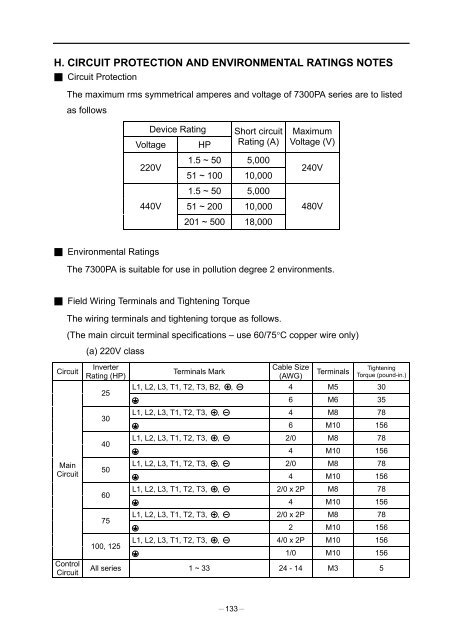
H. CIRCUIT PROTECTION AND ENVIRONMENTAL RATINGS NOTES Circuit ProtectionThe maximum rms symmetrical amperes and voltage of 7300PA series are to listedas followsDevice RatingVoltage HPShort circuitRating (A)MaximumVoltage (V)220V440V1.5 ~ 50 5,00051 ~ 100 10,0001.5 ~ 50 5,00051 ~ 200 10,000201 ~ 500 18,000240V480V Environmental RatingsThe 7300PA is suitable for use in pollution degree 2 environments. Field Wiring Terminals and Tightening TorqueThe wiring terminals and tightening torque as follows.(The main circuit terminal specifications – use 60/75°C copper wire only)(a) 220V classCircuitMainCircuitControlCircuitInverterRating (HP)253040506075100, 125Terminals MarkCable Size(AWG)TerminalsTighteningTorque (pound-in.)L1, L2, L3, T1, T2, T3, B2, , 4 M5 306 M6 35L1, L2, L3, T1, T2, T3, , 4 M8 786 M10 156L1, L2, L3, T1, T2, T3, , 2/0 M8 784 M10 156L1, L2, L3, T1, T2, T3, , 2/0 M8 784 M10 156L1, L2, L3, T1, T2, T3, , 2/0 x 2P M8 784 M10 156L1, L2, L3, T1, T2, T3, , 2/0 x 2P M8 782 M10 156L1, L2, L3, T1, T2, T3, , 4/0 x 2P M10 1561/0 M10 156All series 1 ~ 33 24 - 14 M3 5133