

PA7300 Instruction Manual - TECO-Westinghouse Motor Company
PA7300 Instruction Manual - TECO-Westinghouse Motor Company
PA7300 Instruction Manual - TECO-Westinghouse Motor Company

Create successful ePaper yourself
Turn your PDF publications into a flip-book with our unique Google optimized e-Paper software.
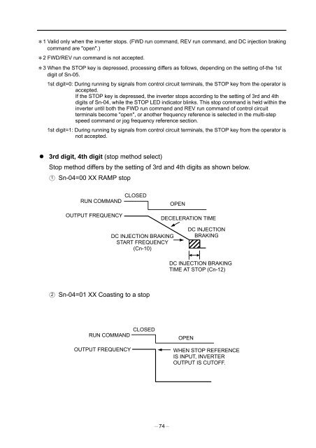
1 Valid only when the inverter stops. (FWD run command, REV run command, and DC injection brakingcommand are "open".)2 FWD/REV run command is not accepted.3 When the STOP key is depressed, processing differs as follows, depending on the setting of-the 1stdigit of Sn-05.1st digit=0: During running by signals from control circuit terminals, the STOP key from the operator isaccepted.If the STOP key is depressed, the inverter stops according to the setting of 3rd and 4thdigits of Sn-04, while the STOP LED indicator blinks. This stop command is held within theinverter until both the FWD run command and REV run command of control circuitterminals become "open", or another frequency reference is selected in the multi-stepspeed command or jog frequency reference section.1st digit=1: During running by signals from control circuit terminals, the STOP key from the operator isnot accepted.3rd digit, 4th digit (stop method select)Stop method differs by the setting of 3rd and 4th digits as shown below.1 Sn-04=00 XX RAMP stopRUN COMMANDOUTPUT FREQUENCYCLOSEDOPENDECELERATION TIMEDC INJECTION BRAKINGSTART FREQUENCY(Cn-10)DC INJECTIONBRAKINGDC INJECTION BRAKINGTIME AT STOP (Cn-12)2 Sn-04=01 XX Coasting to a stopRUN COMMANDOUTPUT FREQUENCYCLOSEDOPENWHEN STOP REFERENCEIS INPUT, INVERTEROUTPUT IS CUTOFF.74


