

PowerPC 740 and PowerPC 750 Microprocessor Datasheet - IBM
PowerPC 740 and PowerPC 750 Microprocessor Datasheet - IBM
PowerPC 740 and PowerPC 750 Microprocessor Datasheet - IBM
- No tags were found...

Create successful ePaper yourself
Turn your PDF publications into a flip-book with our unique Google optimized e-Paper software.
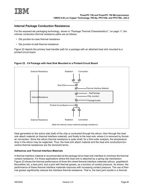
<strong>PowerPC</strong> <strong>740</strong> <strong>and</strong> <strong>PowerPC</strong> <strong>750</strong> <strong>Microprocessor</strong>CMOS 0.20 µm Copper Technology, PID-8p, PPC<strong>740</strong>L <strong>and</strong> PPC<strong>750</strong>L, dd3.2Internal Package Conduction ResistanceFor the exposed-die packaging technology, shown in ”Package Thermal Characteristics1,” on page 11, theintrinsic conduction thermal resistance paths are as follows.• Die junction-to-case thermal resistance• Die junction-to-ball thermal resistanceFigure 22 depicts the primary heat transfer path for a package with an attached heat sink mounted to aprinted-circuit board.Figure 22. C4 Package with Heat Sink Mounted to a Printed-Circuit BoardExternal ResistanceRadiationConvectionInternal ResistanceHeat SinkPrinted-Circuit BoardThermal Interface MaterialDie/PackageChip JunctionPackage/LeadsExternal ResistanceRadiationConvection(Note the internal versus external package resistance.)Heat generated on the active side (ball) of the chip is conducted through the silicon, then through the heatsink attach material (or thermal interface material), <strong>and</strong> finally to the heat sink; where it is removed by forcedairconvection. Since the silicon thermal resistance is quite small, for a first-order analysis, the temperaturedrop in the silicon may be neglected. Thus, the heat sink attach material <strong>and</strong> the heat sink conduction/convectivethermal resistances are the dominant terms.Adhesives <strong>and</strong> Thermal Interface MaterialsA thermal interface material is recommended at the package lid-to-heat sink interface to minimize the thermalcontact resistance. For those applications where the heat sink is attached by a spring clip mechanism,Figure 23 shows the thermal performance of three thin-sheet thermal-interface materials (silicon, graphite/oil,flouroether oil), a bare joint, <strong>and</strong> a joint with thermal grease, as a function of contact pressure. As shown, theperformance of these thermal interface materials improves with increasing contact pressure. The use of thermalgrease significantly reduces the interface thermal resistance. That is, the bare joint results in a thermal9/6/2002 Version 2.0 Page 46


